Remote center of motion robotic system and method

A technology of robots and linkage devices, applied in surgical robots, program-controlled manipulators, manipulators, etc., can solve problems such as limited range of motion and achieve uniform mechanical properties

Inactive Publication Date: 2005-07-20
THE JOHN HOPKINS UNIV SCHOOL OF MEDICINE
View PDF14 Cites 31 Cited by
  • Summary
  • Abstract
  • Description
  • Claims
  • Application Information

AI Technical Summary

Problems solved by technology

There are limitations in the devices in the prior art, and it is expected to improve
In particular, RCM designs with rigid links suffer from limited range of motion

Method used


Image

  • Remote center of motion robotic system and method
  • Remote center of motion robotic system and method
  • Remote center of motion robotic system and method

Examples


Embodiment Construction

[0030] The purpose and technical features of the present invention will be more clearly understood with reference to the following description and accompanying drawings.

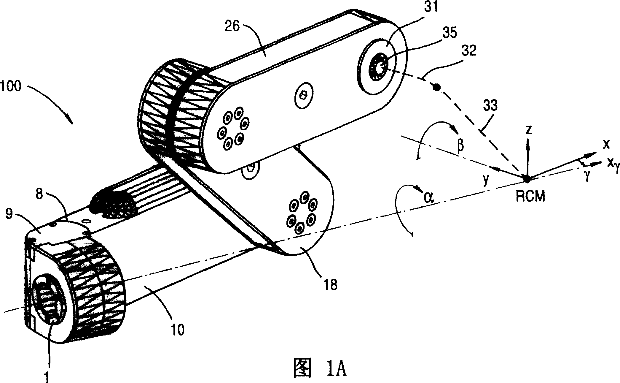
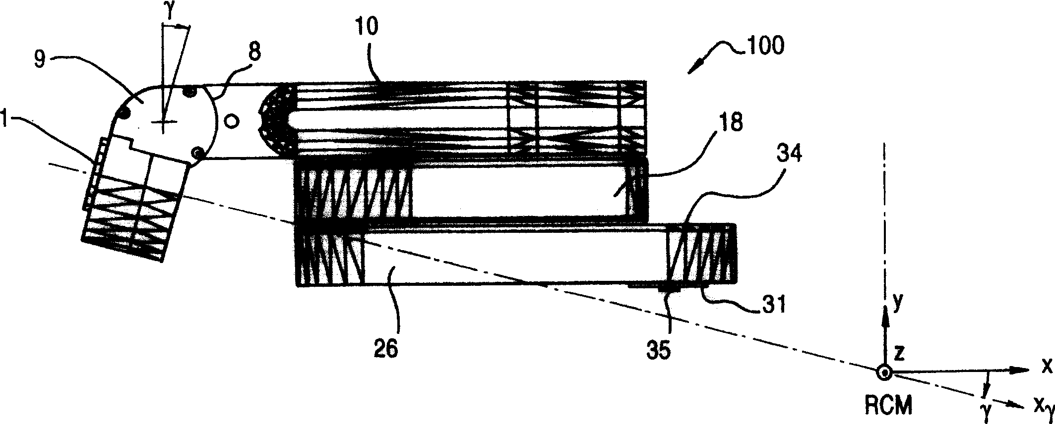
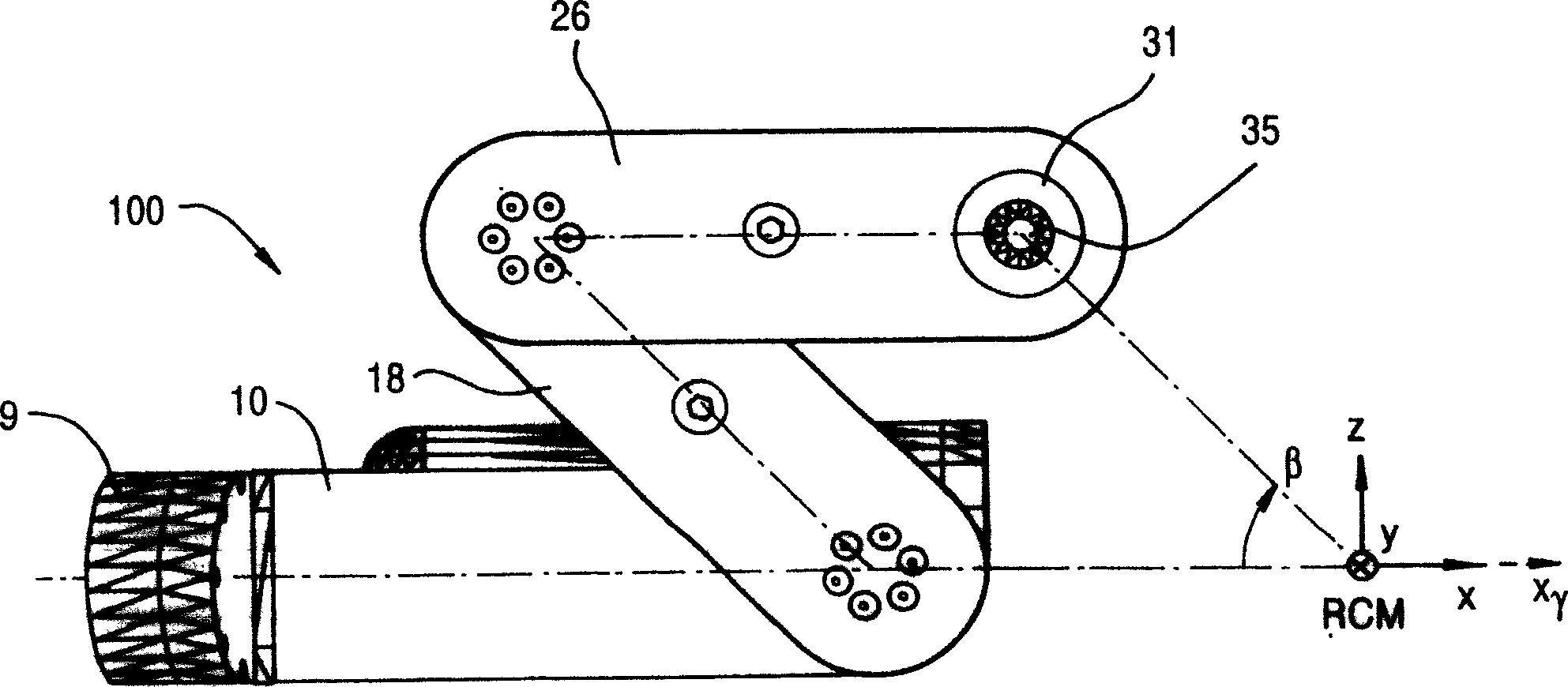
[0031] The present invention provides a novel apparatus and method for performing image-assisted surgery. The present invention includes a robotic device or module that can be used to orient an end effector about two axes that intersect at a fixed geometric point located remote from the mechanical device, specifically a pivot point, referred to as the Remote Center for Motion (RCM) in this manual. An end effector, for example, is a robotic tool such as a needle drive, which can be mounted on the RCM module and can be turned around the RCM point, which is conveniently located on the end effector because this point is far away from the robot module.

[0032] The present invention is designed so that the two axes coincident at the geometric point of the RCM have two rotational degrees of freedom (DOF). The p...


PUM


Abstract

A remote center of motion robotic system including a base unit and a plurality of linking units. The base unit is rotatable about a first axis. The plurality of linking units are coupled with one another. At least two of the linking units are kept parallel to each another during motion. The plurality of linking units are coupled with that base unit at a first end. The plurality of linking units are rotatable about a second axis by changing an angle between each of the plurality of links.

Description

[0001] This application claims the priority of patent application No. 60 / 354,656 filed in the United States on February 6, 2002, entitled "ADJUSTABLE REMOTE CENTER OF MOTION ROBOTIC MODULE", and the full text of the priority application document is used as a reference in this specification. technical field [0002] The present invention relates to robotic devices and methods. In particular, the present invention relates to apparatus and methods for orienting an end effector about two axes intersecting at a fixed geometric point at a location remote from the apparatus, in particular A pivot point or Remote Center of Motion (RCM). Background technique [0003] In the field of robotics, the pivot point and movement principle used is often called RCM. Apparatus and methods for orienting components, tools, and devices about an RCM point remote from a facility are known in the art. See, for example, US Pat. [0004] The RCM principle is commonly used in freehand surgery. In ro...

Claims


Application Information

Patent Timeline
Patent Type & Authority Applications(China)
IPC IPC(8): B25J9/00A61B19/00B25J9/06B25J9/10B25J17/02B25J18/00
CPCY10T74/20323Y10T74/20329B25J18/007A61B2019/2234A61B19/2203A61B2019/265Y10T74/20317A61B2019/2242B25J17/025B25J9/06B25J9/102B25J9/104A61B2019/2246A61B2034/715A61B2090/506A61B34/71A61B34/30A61B2034/305
Inventor 丹尼尔·斯托拉诺维奇路易斯·李·怀特寇姆波都米出·马斯李如斯修·赫·泰勒路易斯·让·卡福斯
Owner THE JOHN HOPKINS UNIV SCHOOL OF MEDICINE
Why Eureka
Try Eureka