Supercharge Your Innovation With Domain-Expert AI Agents!

Electrical connector

A technology of electrical connectors and circuit boards, which is applied in the direction of connection, fixed connection, and installation of connecting parts, etc., to achieve the effect of small and simple structure

Inactive Publication Date: 2005-08-03
FOXCONN (KUNSHAN) COMPUTER CONNECTOR CO LTD +1
View PDF1 Cites 2 Cited by
  • Summary
  • Abstract
  • Description
  • Claims
  • Application Information

AI Technical Summary

Problems solved by technology

This will cause additional stress on the solder joint between the conductive terminal soldering part and the circuit board

Method used


Image

  • Electrical connector
  • Electrical connector
  • Electrical connector

Examples


Embodiment Construction

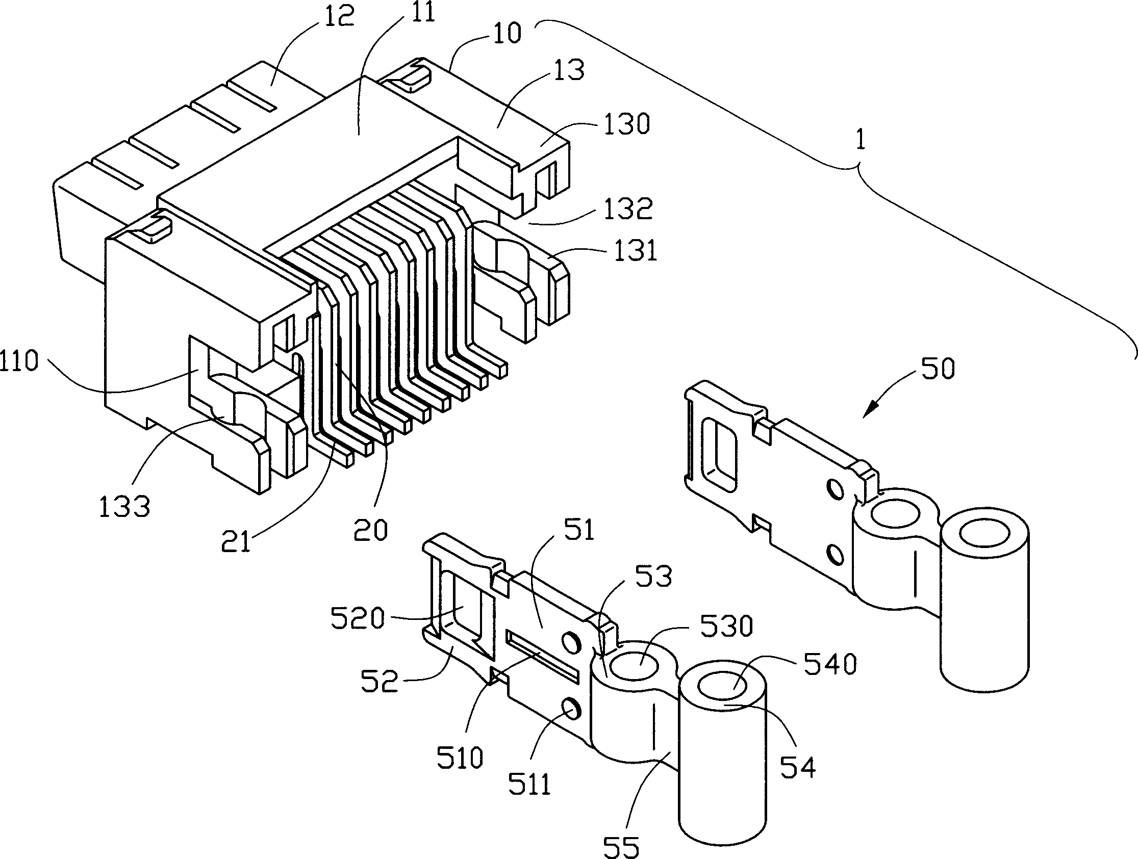
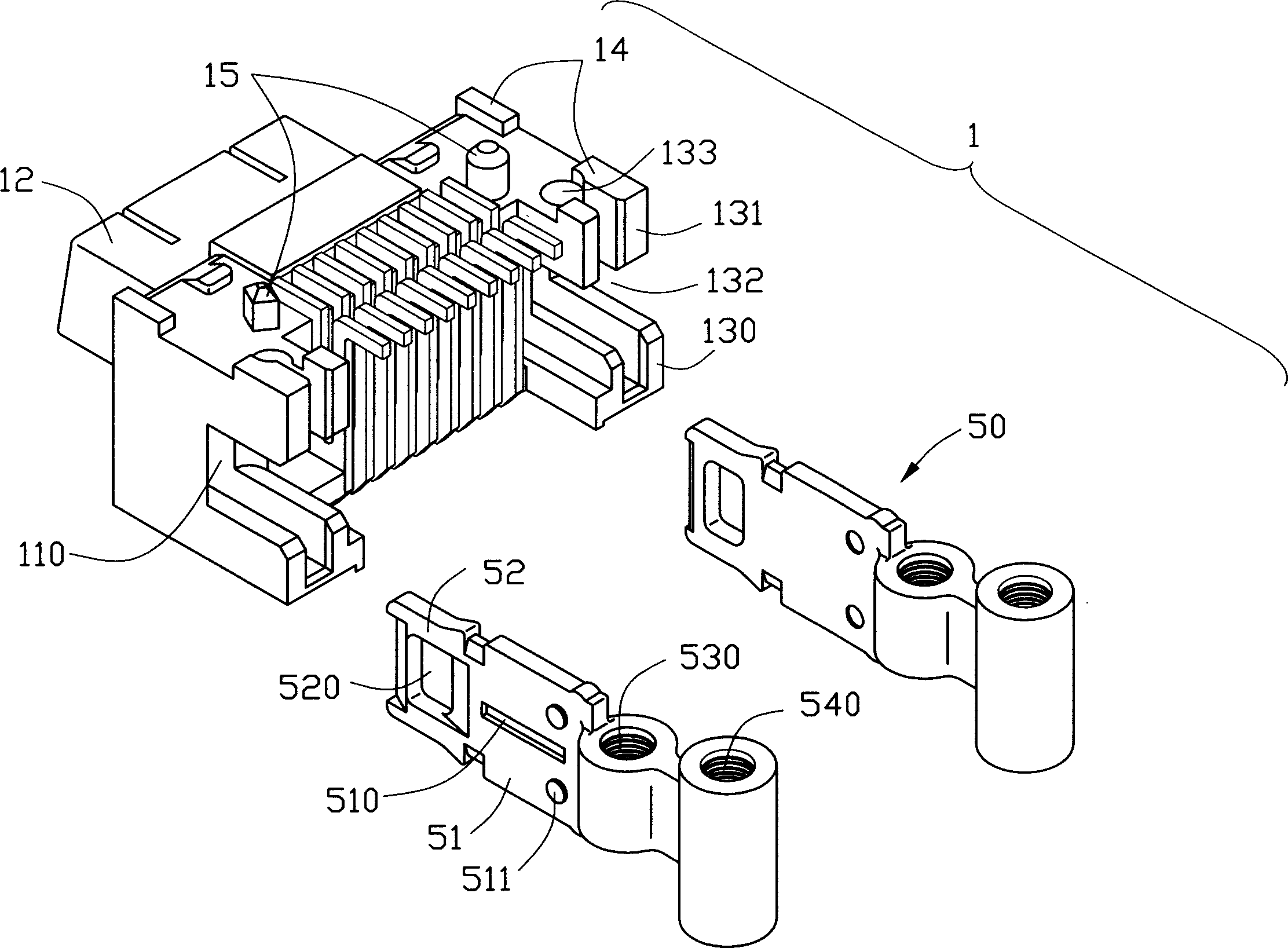
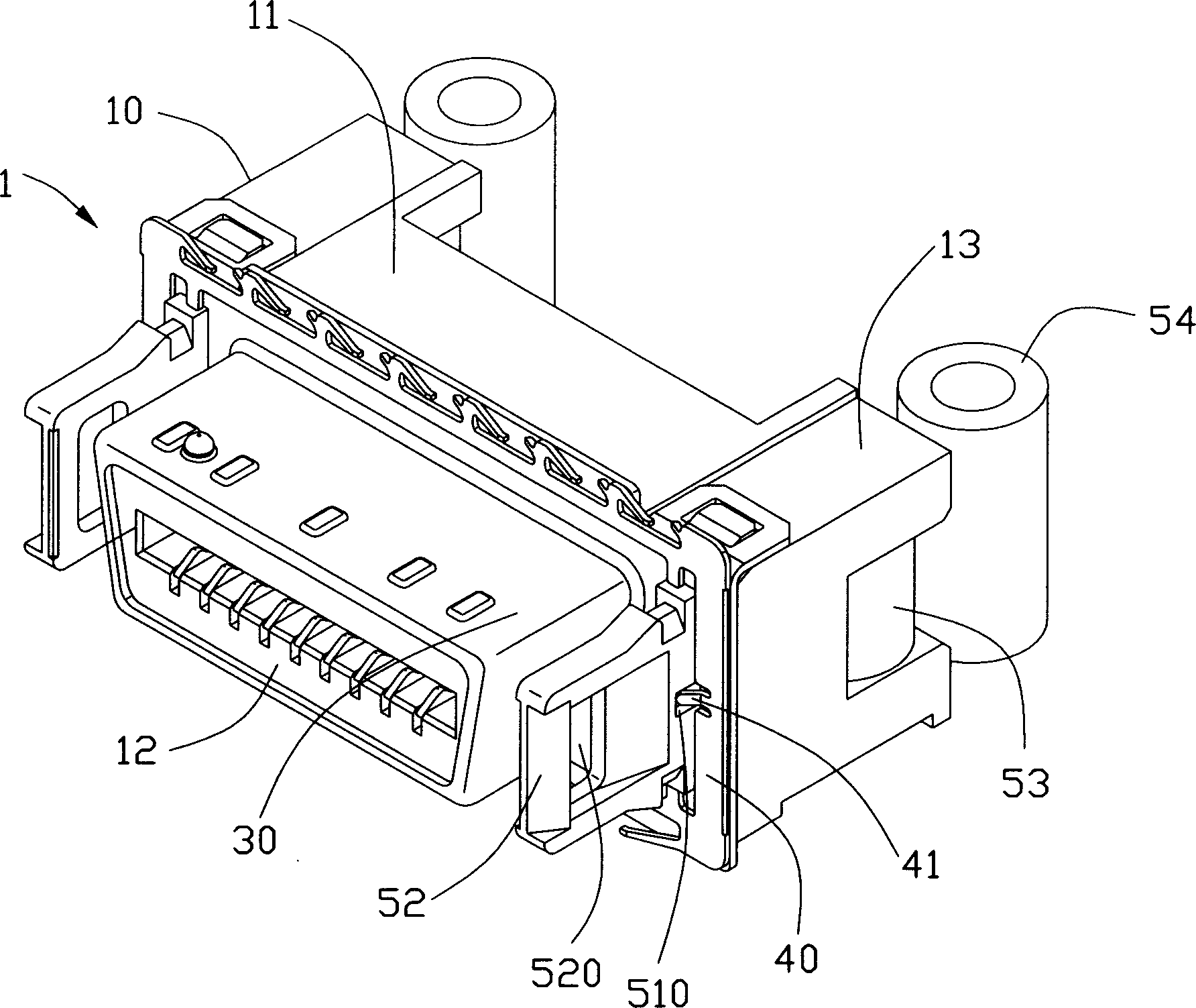
[0014] see Figure 1 to Figure 4 As shown, the electrical connector 1 of the present invention includes an insulating body 10 , a plurality of conductive terminals 20 , a shielding shell 30 , a gasket 40 and a pair of holding devices 50 .

[0015] The insulating body 10 includes a substantially rectangular base 11, a butt joint 12 extending forward from the base 11, a pair of supporting portions 13 extending backward from opposite ends of the base 11, and several The fulcrum 14 and a pair of positioning columns 15 extend downward from the bottom of the base 11 . Each supporting portion 13 includes an upper arm 130 and a lower arm 131 . A cavity 132 is provided between the upper and lower arms 130 , 131 . A pair of retaining grooves 110 extend backward from the front end of the base 11 and on opposite sides of the docking portion 12 , between the upper and lower arms 130 , 131 of the supporting portion 13 to communicate with the cavity 132 . Each lower arm 131 defines a thro...


PUM


Abstract

An electrical connector ( 1 ) includes an insulative housing ( 10 ), a number of contacts ( 20 ) received in the insulative housing, and a pair of securing members ( 50 ). The insulative housing includes a pair of support portions ( 13 ) at opposite ends thereof. Each of the support portions defines a cavity ( 132 ) and a through hole ( 133 ) communicating with the cavity. The securing members are mounted on the opposite ends of the insulative housing. Each of the securing members includes a mounting boss ( 53 ) received in a corresponding cavity of the insulative housing and defining a threaded hole ( 530 ) aligning with the through hole of the insulative housing adapted for engaging with a bolt ( 70 ) to mount the electrical connector on a printed circuit board ( 60 ).

Description

【Technical field】 [0001] The invention relates to an electrical connector, especially an electrical connector with a pair of holding devices for mounting on a circuit board. 【Background technique】 [0002] In personal computers or other electronic devices, electrical connectors are usually installed on a circuit board to electrically connect the circuit board with other electronic components. There are many methods in the prior art to fix the electrical connector on the circuit board. For example, U.S. Patent No. 6,638,111 discloses an electrical connector mounted on a circuit board, which includes an insulating body, a number of conductive terminals accommodated in the insulating body, a shielding shell wrapped on the insulating body, and assembled on the insulating body. installation components. The mounting assembly includes a pair of perforated mounting sleeves for receiving appropriate fasteners to mount the electrical connector on the circuit board. [0003] However...

Claims


Application Information

Patent Timeline
Patent Type & Authority Applications(China)
IPC IPC(8): H01R13/645H01R13/73
CPCH01R23/7026H01R12/7011H01R12/57H01R12/7029H01R13/6456H01R23/701H01R23/7005H01R12/7005
Inventor 艾瑞克·D·钟瑞特崇·H·易
Owner FOXCONN (KUNSHAN) COMPUTER CONNECTOR CO LTD
Features
  • R&D
  • Intellectual Property
  • Life Sciences
  • Materials
  • Tech Scout
  • Unparalleled Data Quality
  • Higher Quality Content
  • 60% Fewer Hallucinations
Learn More