High building life saving device
A life-saving device, high-rise building technology, applied in life-saving equipment, building rescue and other directions, can solve the problems of low efficiency, inappropriate for the elderly, patients and infants, etc., and achieve the effect of stable transmission, simple structure and firm connection
- Summary
- Abstract
- Description
- Claims
- Application Information
AI Technical Summary
Problems solved by technology
Method used
Image

Examples
specific Embodiment approach 1
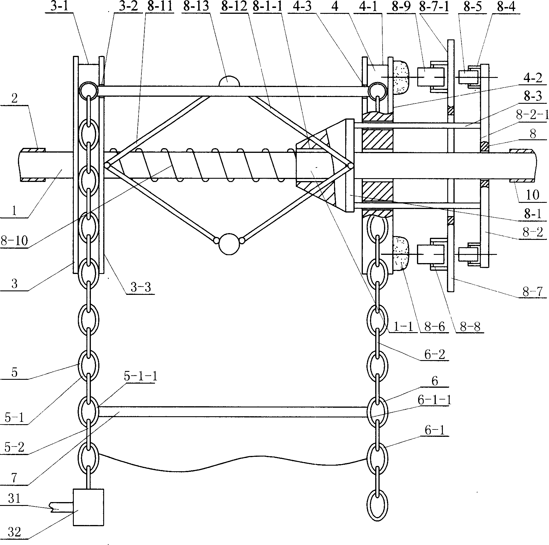
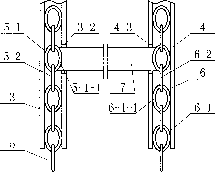
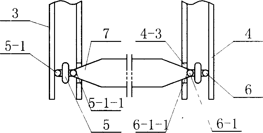
[0006] Specific implementation mode one: combine figure 1 , Figure 8 Describe this embodiment, this embodiment is made up of rotating shaft 1, first sliding bearing 2, second sliding bearing 10, left sprocket 3, right sprocket 4, left chain 5, right chain 6, horizontal bar 7, damping device 8 or centrifugal device 9; the two ends of the rotating shaft 1 are respectively equipped with the first sliding bearing 2 and the second sliding bearing 10, and the rotating shaft 1 inside the first sliding bearing 2 and the second sliding bearing 10 is respectively equipped with the left sprocket 3 And right sprocket wheel 4; There is left groove 3-1 on the outer end face of left sprocket wheel 3, has right groove 4-1 on the outer end face of right sprocket wheel 4, and left ring chain 5 is housed in left groove 3-1 , the right ring chain 6 is housed in the right groove 4-1, the left ring chain 5 meshes with the shape teeth in the left groove 3-1, and the right ring chain 6 meshes with ...
specific Embodiment approach 2
[0007] Specific implementation mode two: combination figure 1 Describe this embodiment, the difference between this embodiment and specific embodiment 1 is: the damping device 8 of this embodiment is composed of a sliding bush 8-1, a side plate 8-2, a flat tie rod 8-3, and a fixed sleeve 8-4 , Outer roller 8-5, sand bag 8-6, block plate 8-7, overcoat 8-8, inner roller 8-9, spring 8-10, left connecting rod 8-11, right connecting rod 8-12, The centrifugal weight 8-13 is composed of; the left end rotating shaft 1 of the right sprocket wheel 4 is equipped with a sliding shaft sleeve 8-1, and the right end rotating shaft 1 of the right sprocket wheel 4 is equipped with a side disc 8-2, and the sliding shaft sleeve 8-1 is connected with the side disc One group of flat tie rods 8-3 is fixed between 8-2, outer roller 8-5 is housed in the fixed sleeve 8-4 of the left end face 8-2-1 of side plate 8-2, the right end face 4- of right sprocket wheel 4 2 is fixed with sand bag 8-6, is prov...
specific Embodiment approach 3
[0008] Specific implementation mode three: combination Figure 8 Describe this embodiment, the difference between this embodiment and specific embodiment one is: the centrifuge device 9 of this embodiment consists of a left shaft sleeve 9-1, a right shaft sleeve 9-2, a compression spring 9-3, and a heavy wheel 9- 4. The left pull rod 9-5, the right pull rod 9-6, the sand bag 9-11, and the bracket 9-12 are composed; the left shaft sleeve 9-1 is respectively arranged on the rotating shaft 1 between the left sprocket 3 and the right sprocket 4 And right axle sleeve 9-2, compression spring 9-3 is housed on the rotating shaft 1 between left axle sleeve 9-1 and right axle sleeve 9-2, and the right end face 9-1-1 of left axle sleeve 9-1 and left The left end of pull bar 9-5 is hinged, and the left end face 9-2-1 of right axle sleeve 9-2 is hinged with the right end of right pull bar 9-6, and the right end of left pull bar 9-5 and the left end of right pull bar 9-6 are respectively co...
PUM
 Abstract
Description
Claims
Application Information
 - R&D Engineer
- R&D Manager
- IP Professional
- Industry Leading Data Capabilities
- Powerful AI technology
- Patent DNA Extraction
Browse by: Latest US Patents, China's latest patents, Technical Efficacy Thesaurus, Application Domain, Technology Topic.
© 2024 PatSnap. All rights reserved.Legal|Privacy policy|Modern Slavery Act Transparency Statement|Sitemap