Real-time tractography

A voxel and feature vector technology, applied in the field of medical imaging, can solve the problem of wasting reconstruction time and achieve the effect of improving the calculation speed

Inactive Publication Date: 2005-08-10
KONINK PHILIPS ELECTRONICS NV
View PDF0 Cites 8 Cited by
  • Summary
  • Abstract
  • Description
  • Claims
  • Application Information

AI Technical Summary

Problems solved by technology

Wasted refactoring time when data is useless

Method used


Image

  • Real-time tractography
  • Real-time tractography
  • Real-time tractography

Examples


Embodiment Construction

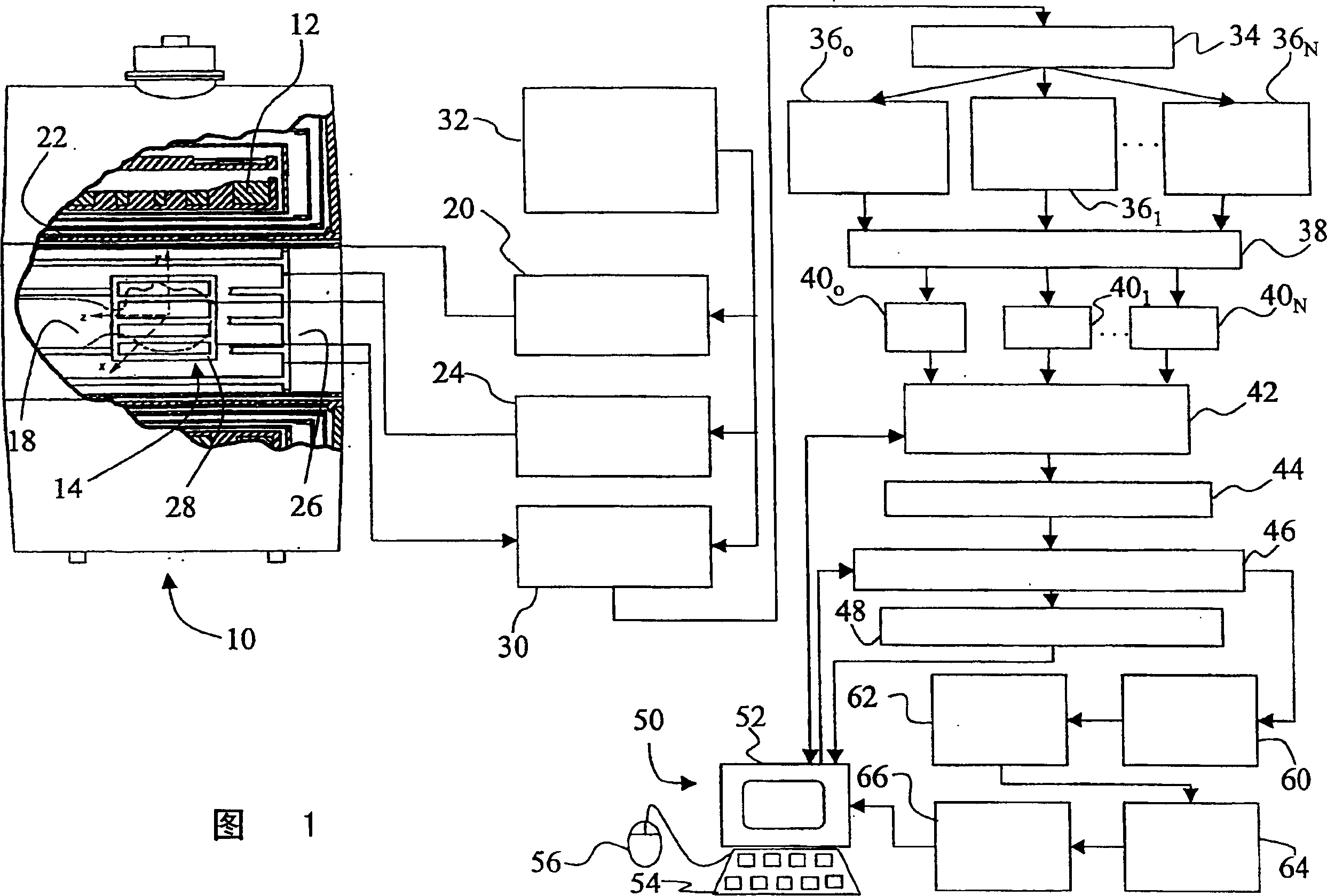
[0019] DETAILED DESCRIPTION OF THE PREFERRED EMBODIMENT

[0020] Referring to FIG. 1 , a magnetic resonance imaging (MRI) scanner 10 generally includes a superconducting or resistive magnet 12 that forms a substantially uniform and temporally constant main magnetic field B0 along the z-axis of an examination region 14 . Although a hole-type magnet is shown in Figure 1, the present invention may also be applied to open magnet systems and other types of MRI scanners. Imaging is performed by performing a magnetic resonance excitation and readout sequence on the subject being imaged (eg, patient 18 ) placed at least partially within examination region 14 (usually the site of interest is at the isocenter of magnet 12 ). For diffusion tensor MRI imaging of the brain, the patient's head is preferably placed on an isocenter point.

[0021] The magnetic resonance sequence includes a series of RF and magnetic field gradient pulse sequences that are applied to subject 16 to control and ...


PUM


Abstract

An imaging method for imaging a subject (18) including fibrous / anisotropic structures (102) includes acquiring three-dimensional image representations without and with a plurality of different diffusion weightings and directions. When a user (56) hovers a selection device over a voxel of the image, a fiber representation (54) is extracted in substantially real time. The representation is generated by following a direction of a major eigenvector e1 from voxel to voxel. A human-viewable display of the fiber representation is produced (210).

Description

Field of Invention [0001] The present invention relates to the field of medical imaging. Specifically, it involves the imaging, tracking, and visualization of nerve fibers and fiber tracts by diffusion tensor magnetic resonance imaging (DT-MRI), and is described with a specific reference. However, the present invention may also be applied in conjunction with other types of fibrous structure tracking and graphic reproduction and other imaging modalities. Background technique [0002] Nervous tissue in humans and other mammals includes nerves with elongated axonal portions configured to form nerve fibers or fiber bundles that transmit electrical signals therealong. For example, areas in the brain delimited by very high neural density are often linked by neural networks of complex axonal fiber bundles. Axonal fiber bundles and other fibrous materials are substantially surrounded by other tissues. [0003] The diagnosis of neurological diseases, the planning of brain surgery ...

Claims


Application Information

Patent Timeline
Patent Type & Authority Applications(China)
IPC IPC(8): G01R33/54A61B5/055G01N24/08G01R33/56G01R33/563G06T5/00G06T15/08G06T17/00
CPCG06T2207/10092G01R33/56341G06T2207/30016G06T2207/20221G06T5/50G06T15/08
Inventor A·M·C·范穆斯温克R·F·J·霍图伊泽恩
Owner KONINK PHILIPS ELECTRONICS NV
Why Eureka
Try Eureka