
Diaphragm unit

一种隔膜、区域的技术,应用在隔膜单元领域,能够解决不均匀施加、未提到凸面区域和凹面区域的曲率半径、减少隔膜耐久性等问题

Inactive Publication Date: 2005-08-17
TOYOTA IND CORP
View PDF1 Cites 4 Cited by
  • Summary
  • Abstract
  • Description
  • Claims
  • Application Information

AI Technical Summary

Problems solved by technology

Therefore, the stress caused by the bending moment is unevenly applied to the diaphragm, and thus reduces the durability of the diaphragm
The above prior art also does not mention any suitable values ​​for the radii of curvature of the convex and concave regions

Method used


Image

  • Diaphragm unit

Examples


Embodiment Construction

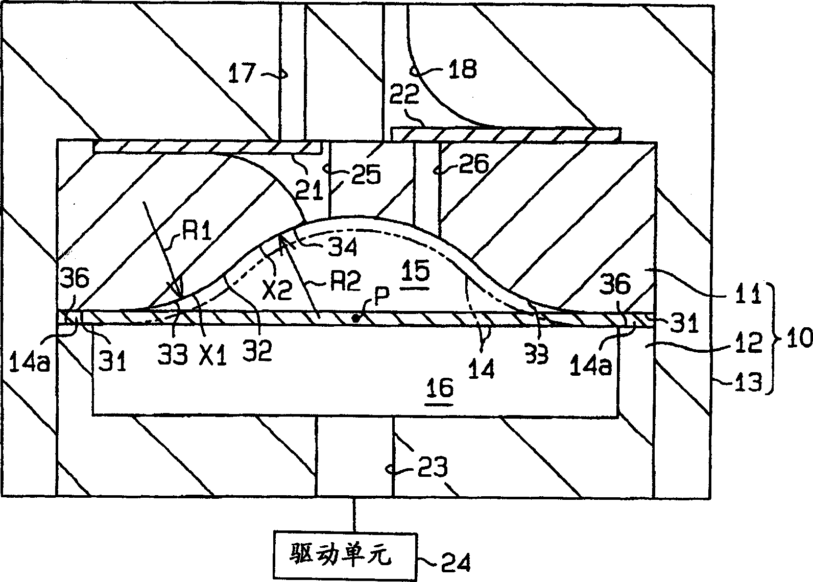
[0015] Below, based on figure 1 A diaphragm unit of a preferred embodiment of the present invention is described. The diaphragm unit in the example shown in this embodiment is used for a diaphragm pump suitable for air supply.

[0016] figure 1 A longitudinal sectional view of a diaphragm pump. Such as figure 1 As shown, the diaphragm pump has a diaphragm housing 10, the diaphragm housing 10 includes a first housing 11, a second housing 12 fixedly connected to the first housing 11, and a main body housing 13, the first housing 11 and The second case 12 is housed in the main body case 13 . Such as figure 1 As shown, the main body case 13 is formed in a cylindrical cover shape with a cover portion at the upper portion. The first and second housings 11 and 12 are accommodated in the main body housing 13 such that the first housing 11 is on the cover side.

[0017] The first housing 11 and the second housing 12 define a space therebetween, and this space is divided into a f...


PUM


Abstract

A diaphragm unit includes a diaphragm and a diaphragm case. The diaphragm has a center point and an outer peripheral portion. The diaphragm case includes a fixing surface and a regulating surface. The fixing surface supports the diaphragm at the outer peripheral portion thereof, thereby defining a fluid chamber in the diaphragm case. The regulating surface forms an inner surface of the fluid chamber, thereby providing a limit of deformation of the diaphragm. The regulating surface has a convex surface region and a concave surface region. The convex surface region is formed continuously with the fixing surface for supporting the diaphragm at a portion thereof adjacent to the outer peripheral portion. The concave surface region is formed continuously with the convex surface region for supporting the diaphragm at a portion thereof adjacent to the center point. Curvatures of the convex and concave surface regions are the same.

Description

technical field [0001] The invention relates to a diaphragm unit, such as a diaphragm pump or a diaphragm damper. Background technique [0002] For example, an internal combustion engine in which fuel is injected into cylinders of the engine is equipped with a pulsation reducing device such as a diaphragm damper (or damper) to stabilize fuel injection by reducing pulsation of fuel supplied by a high-pressure pump. Japanese Unexamined Patent No. 11-62771 discloses such a diaphragm pump (see FIGS. 2-4 thereof). [0003] In the above-mentioned diaphragm damper, the diaphragm is supported at the outer peripheral portion by the fixing surface (or connecting surface) of the damper case. A fluid chamber and a back pressure chamber are formed in the damper housing bounded by a diaphragm. The fluid chamber is connected with a fuel passage extending between the high pressure pump and the cylinder. The back pressure chamber is airtightly filled with high pressure gas. If a pulsatio...

Claims


Application Information

Patent Timeline
Patent Type & Authority Applications(China)
IPC IPC(8): F16L55/04F02M55/00F02M55/02F04B43/00F04B43/02F04B43/06F16J3/02
CPCF04B43/0054F04B43/06F02M55/00F02M55/02
Inventor 山本真也藏本觉桑原卫
Owner TOYOTA IND CORP
Features
  • Generate Ideas
  • Intellectual Property
  • Life Sciences
  • Materials
  • Tech Scout
  • Unparalleled Data Quality
  • Higher Quality Content
  • 60% Fewer Hallucinations
Learn More