Pivoting electromagnetic actuator and integrated actuator and fluid flow control valve

A technology of fluid flow and actuators, which is applied in the direction of electromagnets, electromagnetic relays, and electromagnets with armatures, etc., and can solve the problems of actuators not having fast response time, wear, and shortening device life.

Inactive Publication Date: 2005-08-17
CAMCON OIL LTD
View PDF1 Cites 6 Cited by
  • Summary
  • Abstract
  • Description
  • Claims
  • Application Information

AI Technical Summary

Problems solved by technology

However, no attempt was made to store energy during the movement of the armature
The actuator therefore does not have a fast response time
In addition, when the armature is transferred from one pair of poles to the other, it will impact the new pole and cause significant wear, shortening the life of the device

Method used


Image

  • Pivoting electromagnetic actuator and integrated actuator and fluid flow control valve
  • Pivoting electromagnetic actuator and integrated actuator and fluid flow control valve
  • Pivoting electromagnetic actuator and integrated actuator and fluid flow control valve

Examples


Embodiment Construction

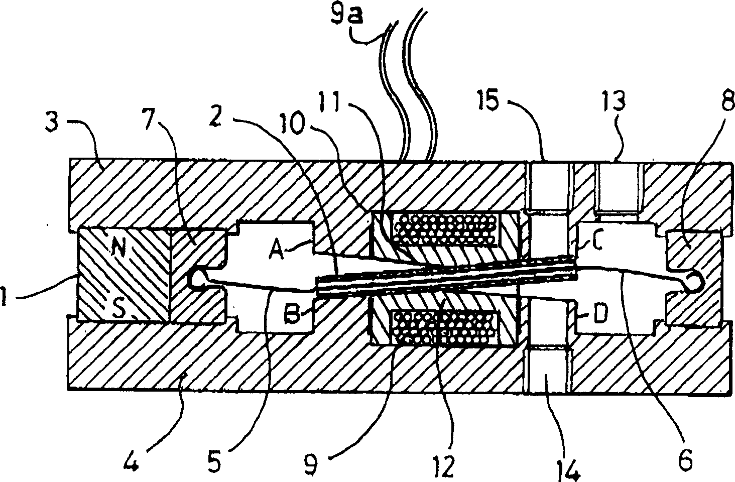
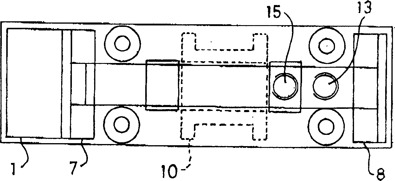
[0098] exist figure 1 and 2 Among them, the components are represented as follows: permanent magnet 1, swing armature 2, pole pieces 3, 4, springs 5, 6, spring holders 7, 8, coil 9, coil terminal 9a, coil body 10, swing edge 11, 12, entrance 13, exit 14, 15.

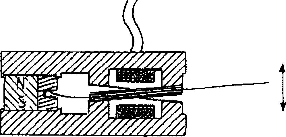
[0099] figure 1 The actuator represents a novel pulse-driven bistable device in which the movement of the ferromagnetic armature 2 is controlled by spring extensions 5, 6 anchored in two non-magnetic holders 7, 8 and formed in the coil body 10. The swinging edges 11, 12 are constrained in one plane. The armature will remain in one or the other of two steady state positions defined by poles A and D or B and C. The permanent magnet 1 provides the static magnetic flux and oscillates by changing the polarity of the armature and the balance between the magnetic flux connecting the poles and opposite ends of the armature.

[0100] This is achieved by a coil 9 mounted around the armature 2 which generates a local magneti...


PUM


Abstract

A magnetic device is formed from a permanent magnet generating magnetic flux, an armature which can occupy two positions between four poles and an electromagnet winding to which current can be supplied to produce a magnetic flux in one direction or the other, the flux from the winding causing the armature to move into one position and continue to remain in that position after the current flow ceases. The device can be incorporated into a fluid valve to act as a drive for opening and closing the valve. It may also serve as the drive for opening and closing electrical contacts. Monostable operation can be achieved by locating a magnetic flux shunt at one end of the armature travel. A holding solenoid may be incorporated. A pivoting armature in a fluid tight chamber comprises a fluid flow controlling device. It can adopt either of two home positions in contact with two magnetic poles and is retained by magnetic flux from a permanent magnet. Fluid can flow into and out of the chamber via a first passage. A second passage extends through one of the poles to an opening in the pole face which is covered by the armature when the latter occupies one home position but is uncovered when the armature occupies its other home position. A third fluid passage extends through and leads to a second opening in another pole, which is covered when the armature occupies its said other home position. Passages in the poles house energy storing springs each of which is compressed as the armature approaches the pole. A push rod can extend through a passage in one of the poles for conveying armature movement externally of the device.

Description

technical field [0001] The present invention relates to an electromagnetic actuator, and more particularly to an actuator structure that can be integrated in a fluid flow control valve. Background technique [0002] UK1513966 describes an electromagnetic conversion device, the patent's Figure 10 and 11 Such a device is shown in which the armature 3 is oscillating between two points under the influence of currents caused by changes in the magnetic flux connecting the armature to the four poles 6, 6', 7 and 7'. exist Figure 11 In , the spring is shown permanently connecting one end of the armature between the two poles to center the armature between the poles. Examples of centering springs are shown in Figures 12 and 13. [0003] in UK1513966 Figure 10 and 11 In both arrangements shown, the layer of non-magnetic material forming the body of the coil is located between the ends of the magnet and the magnetic material forming the respective poles 6, 6', 7 and 7'. This si...

Claims


Application Information

Patent Timeline
Patent Type & Authority Applications(China)
IPC IPC(8): F16K31/06F16K31/08H01F7/08H01F7/122H01F7/16H01H51/22
CPCH01H51/2209F16K31/0682F16K31/082H01F7/081H01F7/1615
Inventor W·维南斯基
Owner CAMCON OIL LTD
Why Eureka
Try Eureka