Electroluminescent device

An electroluminescent device and electroluminescent layer technology, applied in electroluminescent light sources, electric light sources, lighting devices, etc., can solve the problems of reduced brightness and/or efficiency of displays, energy consumption, etc., and achieve satisfactory brightness and / or the effect of efficiency, good contrast

Inactive Publication Date: 2005-08-17
KONINKLIJKE PHILIPS ELECTRONICS NV
View PDF7 Cites 3 Cited by
  • Summary
  • Abstract
  • Description
  • Claims
  • Application Information

AI Technical Summary

Problems solved by technology

[0005] A disadvantage of the known displays described is that the increase in contrast leads to a significant reduction in the brightness and / or efficiency of the display (if the same brightness is to be obtained, the drive current must be increased, thus consuming more energy), because the circular polarizer absorbs About half of the unpolarized light emitted from the light-emitting layer

Method used


Image

  • Electroluminescent device
  • Electroluminescent device
  • Electroluminescent device

Examples


Embodiment Construction

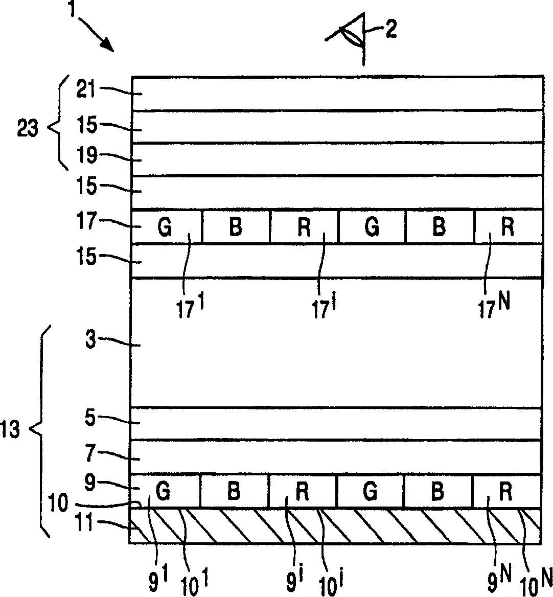
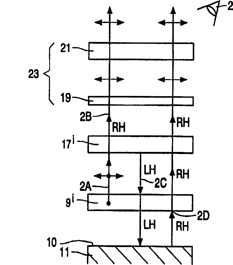
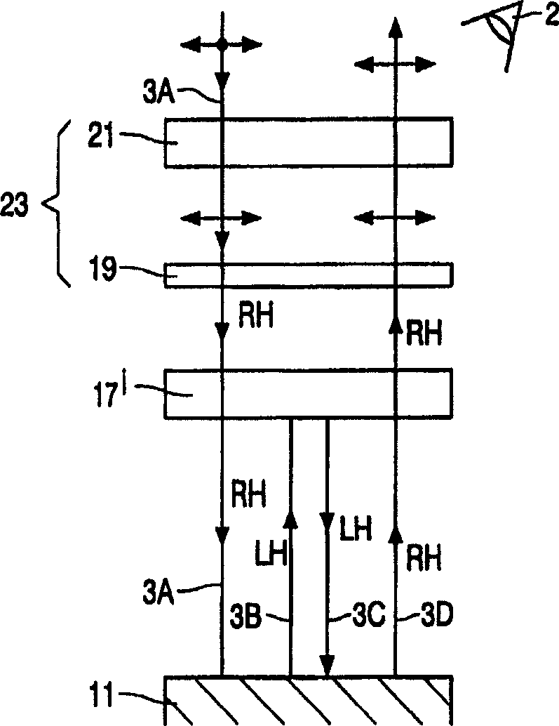
[0039] figure 1 An embodiment of an electroluminescent device according to the invention is schematically shown in cross-section. figure 1 The electroluminescent device 1 shown in includes a conventional polymer or organic light emitting diode (LED) 13 . It is not necessary to use a polymer or organic LED 13, any other electroluminescent device may be used to illustrate the invention. LEDs are particularly well suited to illustrate the invention because they typically include electrodes that specularly reflect (ambient and emitted) light with high efficiency. Light-emitting diodes LED 13 successively include:

[0040] a substrate 3 which is transparent at least to the light emitted by the LEID 13;

[0041] The first electrode layer 5 is used to inject the first type of charges (holes or electrons), and the electrode layer 5 is transparent to the light emitted by the LED 13;

[0042] The charge transport layer 7 is used to transport the first type of charge from the electro...


PUM

PropertyMeasurementUnit
thicknessaaaaaaaaaa
thicknessaaaaaaaaaa
thicknessaaaaaaaaaa

Abstract

An electroluminescent device (13), such as a light emitting diode, which has a light-reflecting surface (10) causing undesirable reflection of ambient light incident on the device is provided with a combination of a reflective circular polarizer (17) and an absorbing circular polarizer (23) to suppress the undesirable reflection of ambient light thus improving the contrast of the device when used under high intensity ambient lighting conditions while maintaining a satisfactory brightness. The reflection band of the reflective circular polarizer regions (17') of the reflective circular polarizer (17) are preferably tuned to the corresponding emission band of the luminescent regions (9') of the electroluminescent device to further increase the contrast of the device while substantially maintaining the same brightness.

Description

technical field [0001] The invention relates to an electroluminescent device. Background technique [0002] Electroluminescent (EL) devices are devices that emit light when connected to a voltage source to provide the appropriate voltage. Of particular interest among these are organic electroluminescent devices, or more specifically polymer electroluminescent devices, in which the light-emitting layer is made of an organic or polymeric material, respectively. [0003] Electroluminescent devices are suitable for display, lighting and signaling applications. Organic (polymer) electroluminescent devices are particularly suitable if the device is to be thin and / or emit light over a large surface area. [0004] WO 97 / 38452 discloses an electroluminescent device in the form of a display. The display has a light emitting layer and a light reflecting back electrode. The back electrode reflects ambient light towards the viewer, and since the reflected ambient light does not conta...

Claims


Application Information

Patent Timeline
Patent Type & Authority Applications(China)
IPC IPC(8): H05B33/02G02B5/30G02F1/13357H01L27/32H01L51/50H01L51/52
CPCH01L27/3244H01L27/3281H01L27/3239H01L51/5281H01L27/3211H10K59/221H10K59/35H10K59/12H10K59/17H10K50/86
Inventor D·J·布罗尔H·F·J·J·范通格伦R·J·维斯塞
Owner KONINKLIJKE PHILIPS ELECTRONICS NV
Why Eureka
Try Eureka