Battery pack

A battery pack and battery technology, applied in battery pack components, secondary batteries, primary batteries to battery grouping, etc., can solve problems such as reverse flow into the car

Inactive Publication Date: 2005-08-24
PANASONIC CORP
View PDF0 Cites 13 Cited by
  • Summary
  • Abstract
  • Description
  • Claims
  • Application Information

AI Technical Summary

Problems solved by technology

[0005] However, when the above-mentioned battery pack is installed in an electric vehicle or a hybrid vehicle, the air taken in from the inside of the vehicle is usually drawn into the case 22 as cooling wind W to cool the battery 21, and the heated cooling wind W is discharged. Therefore, there is a problem that if the battery is abnormal and gas is released into the case 22, the gas released into the case 22 will flow back into the car in the state where the fan is stopped.

Method used


Image

  • Battery pack
  • Battery pack
  • Battery pack

Examples


Embodiment Construction

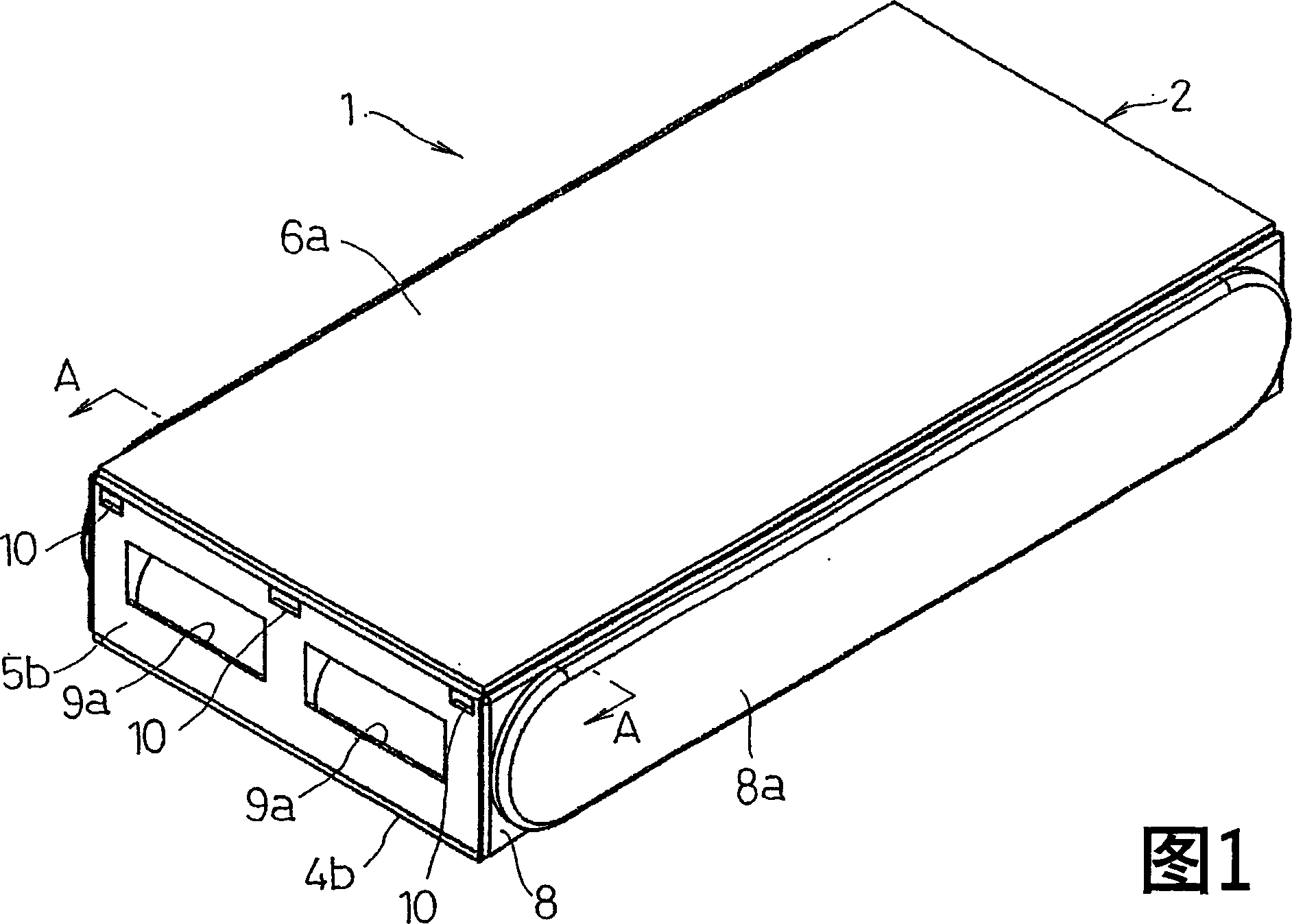
[0020] Hereinafter, an embodiment of the battery pack of the present invention will be described with reference to FIGS. 1 to 7 .

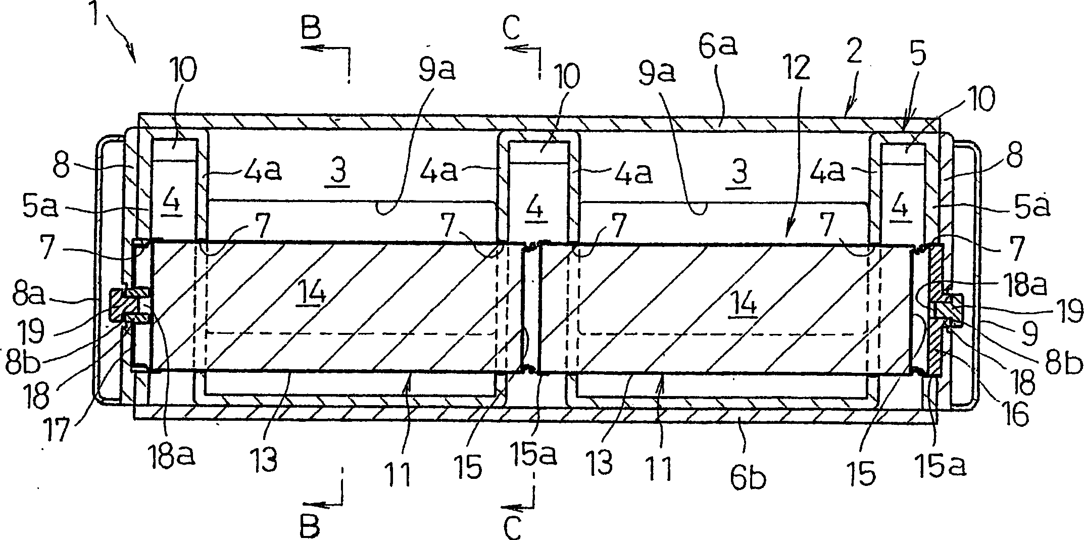
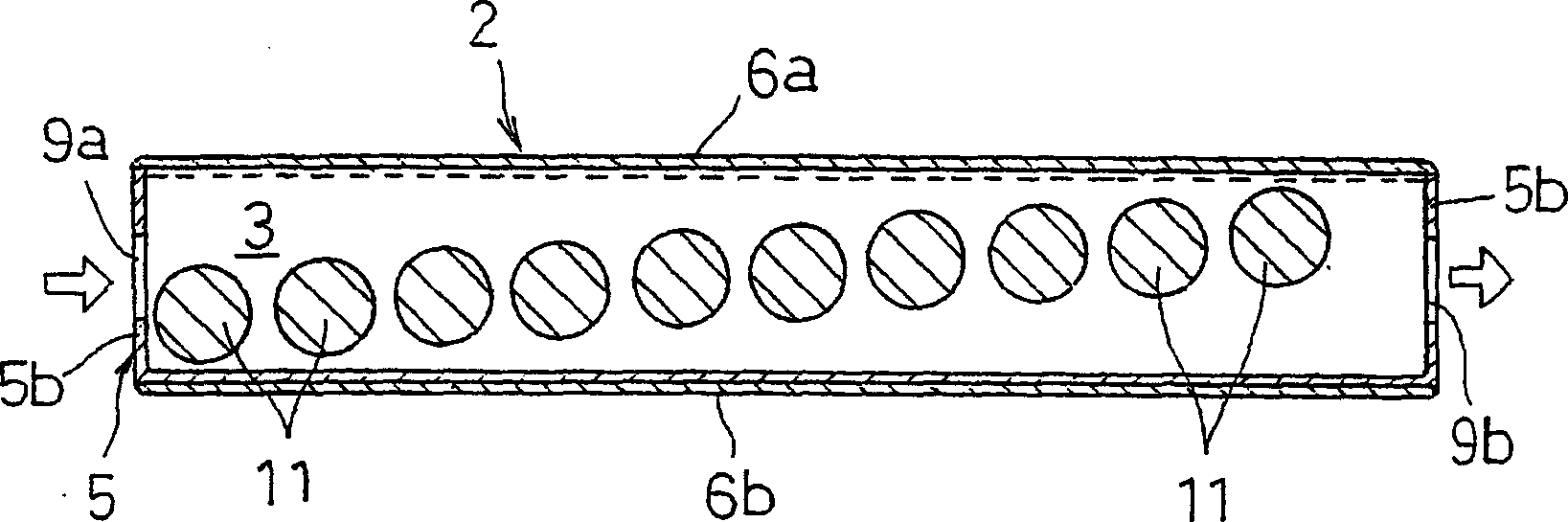
[0021] In Figure 1~ Figure 4 Among them, 1 is a battery pack, which is configured as follows: a plurality of (two in the illustration) batteries are arranged side by side in a flat rectangular parallelepiped casing 2 with an appropriate gap between them. 11. Battery cells 12 (ten in the illustration) formed coaxially are connected in series, and these battery cells 12 are sequentially connected in series.

[0022] In the case 2, the cooling air passage 3 is formed by making the parts of the two batteries 11 of the battery units 12 arranged in parallel face to face, and the ends of the batteries 11 face each other. Gas discharge passages 4 are formed in both side portions of the battery cells 12 in the side-by-side direction of the housing 2 and portions of the battery cells 12 corresponding to the connection portions of the batteries 11 . In or...


PUM


Abstract

In a battery pack ( 1 ) that accommodates a plurality of batteries ( 11 ) arranged in parallel in a case ( 2 ) that forms a cooling-air passage ( 3 ), the cooling-air passage ( 3 ) and a gas-discharge passage ( 4 ) for discharging gas leaking from the battery ( 11 ) when the battery ( 11 ) falls into abnormal state are formed and separated from each other in the case ( 2 ).

Description

technical field [0001] The present invention relates to a battery pack, and particularly relates to a battery pack (Battery Pack) in which a plurality of batteries are arranged side by side in a casing, and cooling air passages are formed in the casing to cool the batteries. Background technique [0002] In recent years, due to global environmental problems, expectations for electric vehicles and hybrid vehicles have been high. As for secondary batteries used as their power sources, in addition to small and light weight, high capacity and high output are also expected. Therefore, A battery pack in which a plurality of batteries composed of single cells are connected in series is used. Also, Japanese Patent Application Laid-Open No. 13-319697 and the like disclose a technique of arranging the batteries side by side in a housing and introducing cooling air from the vehicle interior into the housing in order to cool the batteries. [0003] refer to Figure 8 To explain, the pl...

Claims


Application Information

Patent Timeline
Patent Type & Authority Applications(China)
IPC IPC(8): H01M2/12H01M2/10H01M6/42H01M10/60H01M10/613H01M10/625H01M10/643H01M10/6556H01M10/6563
CPCH01M10/5004H01M10/5022H01M10/5059H01M2/12H01M10/5016H01M10/503H01M2/105H01M10/5067H01M6/42H01M10/613H01M10/625H01M10/633H01M10/643H01M10/6557H01M10/6563H01M50/213H01M50/30Y02E60/10
Inventor 上本诚一木村健治桥本达也藤井隆文行定弘式长谷昌朋
Owner PANASONIC CORP
Why Eureka
Try Eureka