
Electromagnetic buffer

A technology of electromagnetic buffers and buffers, applied in the direction of shock absorbers, shock absorbers, magnetic springs, etc., can solve the problems of increasing the machining process of electromagnetic buffers, motor damage, productivity and production cost effects, and improve processing performance. and productivity, reduced installation parts, and good heat dissipation

Inactive Publication Date: 2005-09-07
KYB CORP +1
View PDF1 Cites 19 Cited by
  • Summary
  • Abstract
  • Description
  • Claims
  • Application Information

AI Technical Summary

Problems solved by technology

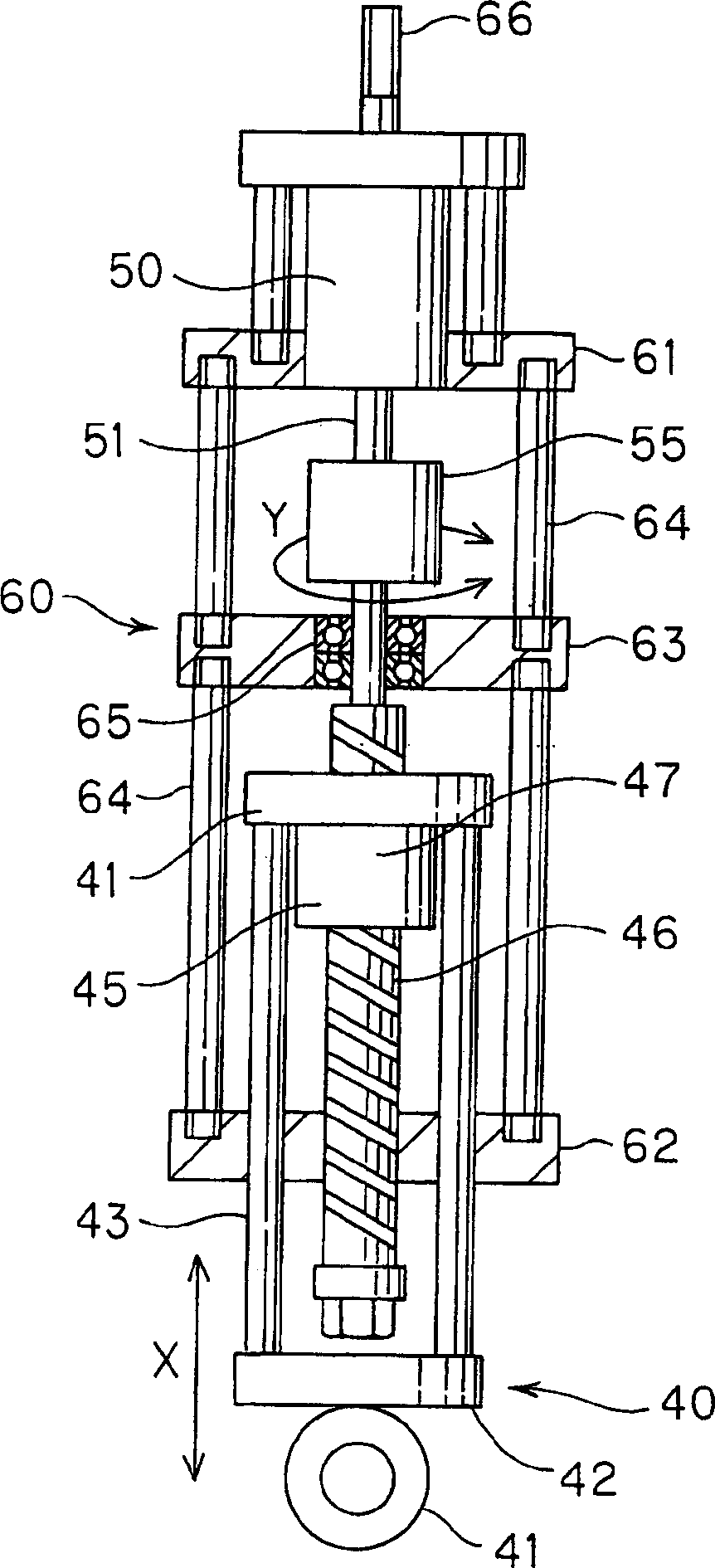
If the temperature of the motor 50 rises further, when it exceeds the rated temperature of the motor 50, the insulating film of the wire forming the coil will undergo a chemical change due to heat, thereby deteriorating the insulation performance. danger
[0022] When enlarging the cover and the outer cylinder of the electromagnetic buffer and enlarging the space around the electric motor 50 in order to avoid damage caused by the temperature rise of the electric motor 50, interference with other components such as frames sometimes occurs, and it is difficult to apply as described above. to the vehicle, and also produces a new disadvantage of the increase in the weight of the electromagnetic buffer itself
[0023] Furthermore, when the motor 50 is used as an independent component, when the motor 50 is mounted on the electromagnetic buffer main body, the number of connecting parts such as bolts and nuts, the bracket for the motor will be increased, and the electromagnetic shock absorber will also be increased. The processing steps of the buffer have a bad influence on productivity and production cost

Method used


Image

  • Electromagnetic buffer
  • Electromagnetic buffer
  • Electromagnetic buffer

Examples


Embodiment Construction

[0037] Next, the present invention will be described based on the embodiments shown in the drawings.

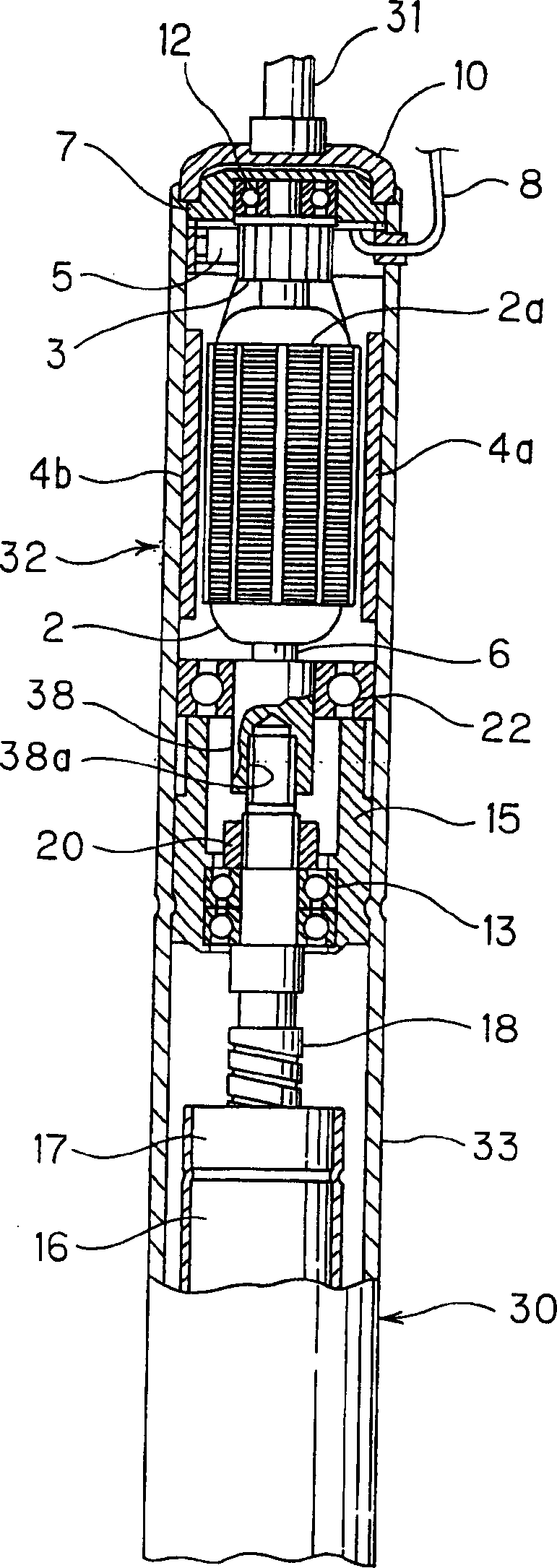
[0038] The damper main body 30 constituting the electromagnetic damper of the present invention includes an outer cylinder 23 into which an inner cylinder 19 is slidably coaxially inserted.

[0039] The motor 32 is arranged above the outer cylinder 23, and the screw shaft 18 constituting the ball screw mechanism 16 is arranged inside the inner cylinder 19, and the ball nut 17 screwed with the screw shaft 18 is fixed to the upper part of the inner cylinder 19. When the inner cylinder 19 expands and contracts relative to the outer cylinder 23 , the screw shaft 18 screwed to the ball nut 17 rotates at this position.

[0040] The shaft 6 of the motor 32 is connected to the screw shaft 18 with a planetary gear mechanism 36 , so that the motor 32 is rotated by the rotation of the screw shaft 18 .

[0041]In this embodiment, the motor 32 is a motor with DC brushes, and consists of ...


PUM


Abstract

A shock absorber body which makes telescopic motion in response to an input from outside has a ball screw mechanism (16) which converts the telescopic motion into rotary motion and is composed of a ball nut (17) and a screw shaft (18). A motor (32) is provided coaxially with the shock absorber body (30). The motor (32) generates electromagnetic resistance to oppose against the rotary motion which inputs into a rotary shaft (6) of the motor. A cylindrical member (1 or 23) which covers the shock absorber body (30) and the motor (32) from outside and whose part covering the motor (30) also serves as a motor frame is provided. Damping force which opposes against the telescopic motion of the shock absorber body (30) is generated according to electromagnetic force of the motor (32).

Description

technical field [0001] The invention relates to an electromagnetic buffer which converts the telescopic motion of the buffer main body into the rotary motion of the motor by using a ball screw mechanism, and attenuates the vibration by using the electromagnetic resistance generated by the motor. Background technique [0002] As a vehicle suspension device, a device in which a hydraulic shock absorber is arranged in parallel with a suspension spring between a vehicle body and an axle is known. [0003] In addition, JP-A-5-44758 discloses a device that incorporates an electromagnetic coil into a part of an oil shock absorber. The device respectively installs the coil on the hydraulic cylinder of the oil pressure buffer, installs the magnet on the piston rod, and energizes the coil to generate a driving force (electromagnetic force) along the stroke direction of the piston rod. According to the vehicle Control the amount of expansion and contraction of the suspension device. ...

Claims


Application Information

Patent Timeline
Patent Type & Authority Applications(China)
IPC IPC(8): F16F15/03
CPCF16F2232/06F16F15/035F16F6/00F16F15/03F16F7/00
Inventor 近藤卓宏松前太郎须田义大
Owner KYB CORP
Learn More