

Automatic clutch
A technology of automatic clutch and centrifugal block, applied in the direction of automatic clutch, clutch, joint control, etc., can solve the problems of complex process, complex structure, unreasonable structure, etc., and achieve the effect of simple operation, simple shape and easy production
Inactive Publication Date: 2005-09-14
孙铁梅
View PDF0 Cites 3 Cited by
- Summary
- Abstract
- Description
- Claims
- Application Information
AI Technical Summary
Problems solved by technology
[0002] At present, except a few high-end cars at home and abroad that use oil-hydraulic automatic clutches with complex processes and expensive costs, most of them use pedal-operated mechanical clutches, but their structures are complex and unreasonable. It is a big trouble: when shifting gears, the right pedal is first lifted (the accelerator is closed), the left pedal is pressed down (the clutch disengages the gearbox from the engine), and at this time the hand shifts; after shifting, Lift up the left foot (the clutch makes the gearbox combined with the engine), press down the pedal with the right foot, supply fuel through the accelerator, and the car operates according to the shifted gear
Method used
View moreImage
Smart ImageViewing Examples

Examples
Embodiment Construction
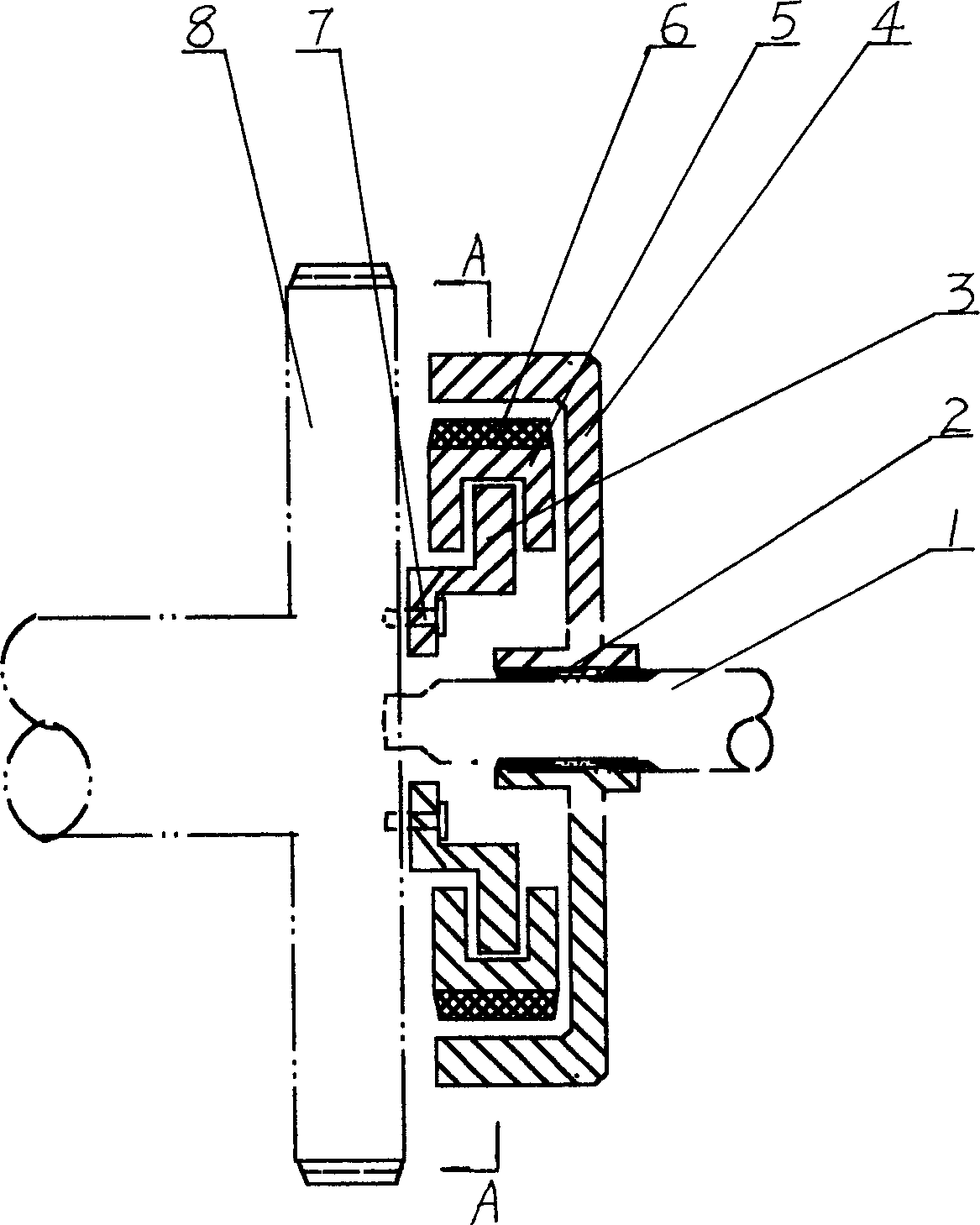
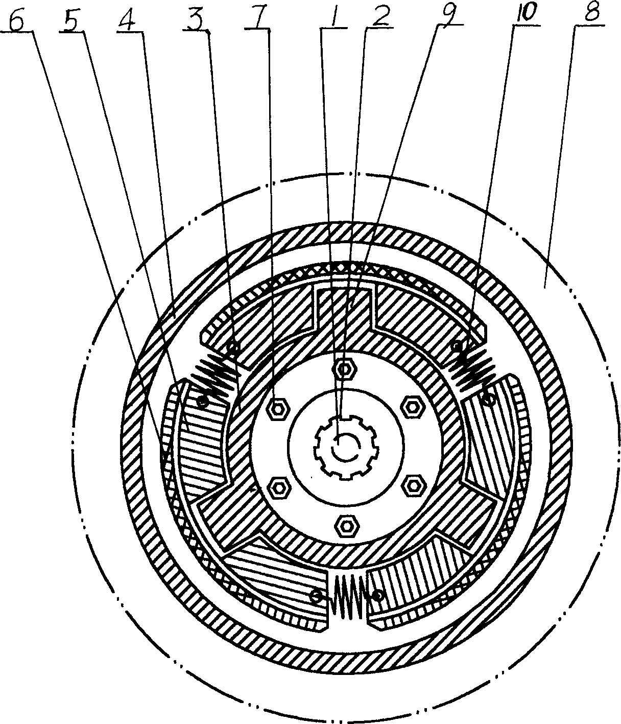
[0010] The present invention includes a centrifugal hub basin 4 with internal splines 2, a centrifugal block frame 3 with a stopper 9 is arranged in the centrifugal hub basin 4, and a centrifugal block with a friction plate 6 is arranged between the centrifugal block frame 3 and the centrifugal hub basin 4 5. A spring 10 is set between the centrifugal blocks 5 .
[0011] Three symmetrical blocks 9 can be set, and three centrifugal blocks 5 can be set accordingly.
[0012] When in use, the centrifugal block frame 3 is fixed on the engine flywheel 8 by screws 7 , and the spline 2 inside the centrifugal hub basin 4 is connected with the input shaft 1 .
Login to View More PUM
 Abstract
The invention relates to an automatic clutch that is the improvement of automobile clutch structure. It includes inner spline centrifuge hub bowl that is set centrifuge block frame in it. And centrifuge blocks are set between the block frame and hub howl. Springs are set between the centrifuge blocks.
Description
Technical field: [0001] The present invention relates to the improvement of the automobile clutch structure. Background technique: [0002] At present, except for a few high-end cars at home and abroad that use complex and expensive oil hydraulic automatic clutches, most of them use foot-operated mechanical clutches, but their structures are complex and unreasonable. There is a big trouble: when shifting gears, firstly the right pedal is lifted (the accelerator is closed), and the left pedal is pressed down (the clutch makes the gearbox disengage from the engine). At this time, the hand shifts; after shifting, The left foot is lifted (the clutch makes the gearbox combine with the engine), the right foot is pressed down on the pedal again, and the fuel is supplied through the accelerator, and the car is operated by the gear that has been changed. On a slope or in a critical situation, due to the driver's nervousness, it is easy to have improper coordination of the left and r...
Claims
Login to View More Application Information
Patent Timeline
 IPC IPC(8): B60K17/02F16D43/04F16D43/14
CPCF16D43/18
Inventor孙铁梅孙广安
Owner孙铁梅