Pulling force auxiliary apparatus for changing main steel cable of elevator

An additional device, the technology of the main steel cable, applied in the direction of transportation and packaging, elevators, etc., can solve problems such as increased self-weight

Inactive Publication Date: 2005-09-28
HITACHI BUILDING SYST CO LTD
View PDF1 Cites 8 Cited by
  • Summary
  • Abstract
  • Description
  • Claims
  • Application Information

AI Technical Summary

Problems solved by technology

[0004] But, in the above-mentioned conventional tension adding device, if the floors of the elevator are many, the length of the established main steel cable or the new main steel cable is just long, so, because of the self-weight increase of the established main steel cable or the new main steel cable, Large, the following problems occur: when the main steel cable of the auxiliary tension attachment device is recovered by the roller to the established main steel cable on the coiling device for recovery of the main steel cable and the main steel cable is supplied from the new main steel cable to the auxiliary tension attachment device The new main steel cable is supplied between the new main steel cables on the side of the lifting road with rollers. Due to the loss of balance of the tension, the new main steel cable falls in the lifting road and is in a drooping state.

Method used


Image

  • Pulling force auxiliary apparatus for changing main steel cable of elevator
  • Pulling force auxiliary apparatus for changing main steel cable of elevator
  • Pulling force auxiliary apparatus for changing main steel cable of elevator

Examples


Embodiment Construction

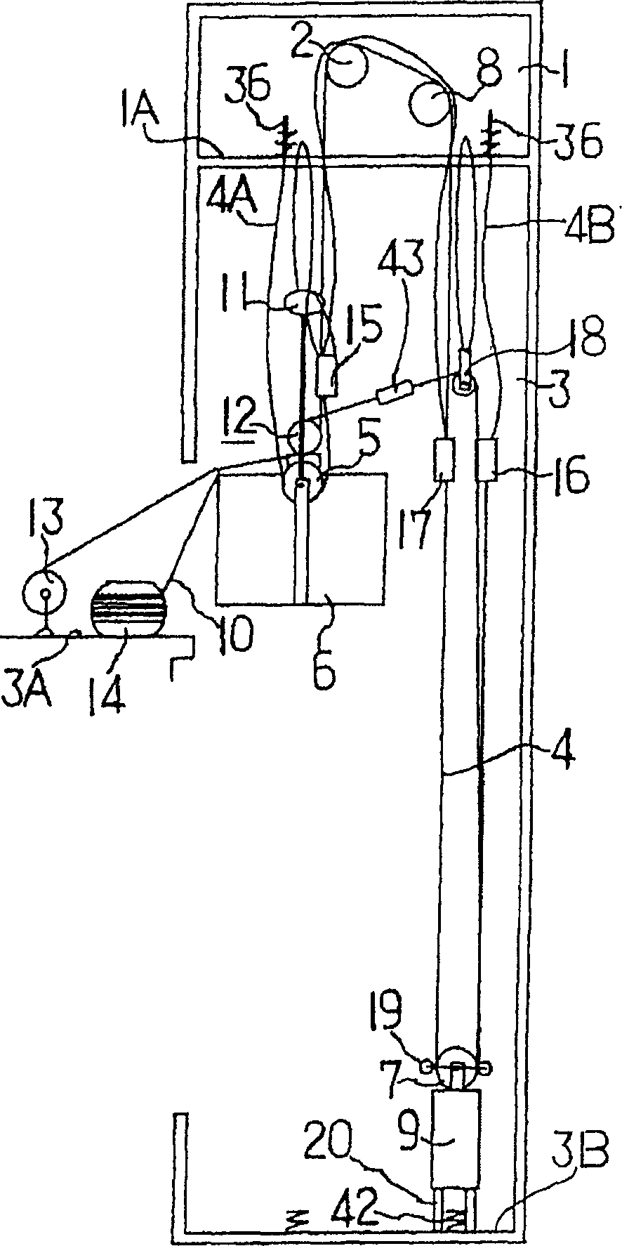
[0018] Embodiments of the main rope replacement tensioning device for an elevator according to the present invention will be described below with reference to the drawings.

[0019] figure 1 The elevator of the shown embodiment is a 2-to-1 roped elevator, and it is equipped with: it is wound on the sheave 2 of the hoist installed in the machine room 1, and its one end 4A and the other end 4B are supported and fixed. A plurality of established main steel cables 4 on the floor of the machine room 1; between an end 4A of the established main steel cables 4 and the winch wheel 2 of the winch, a riding box cooperating with the established main steel cables 4 The riding box 6 supported by the pulley used; between the other end 4B of the established main steel cable 4 and the cable pulley 2 and the deflector wheel 8 of the winch, the reverse pulley 7 coordinated with the established main steel cable 4 Supported counterweight 9.

[0020] exist figure 1 On the elevator of the embodi...


PUM


Abstract

Provided is a tension adding device for main rope replacement work for an elevator in which main rope replacement work can be smoothly performed without causing a main rope to drop in an elevator shaft by weight of the main rope. In this tension adding device for main rope replacement work for elevator, an existing main rope is wound around a drum for the existing main rope, and a new main rope is wound around a drum for the new main rope in such a way that the direction of the existing main rope to be wound around the drum for the existing main rope to be recovered by a winding means for recovering the existing main rope and the direction of the new main rope supplied from a supply drum for the new main rope to be wound around the drum for the new main rope are the same to each other. A brake means 27 is provided to brake the drum 25, 25A, and 25B for the existing main rope and the drum 26, 26A, and 26B for the new main rope.

Description

technical field [0001] The invention relates to a tension attachment device for replacing main steel cables of an elevator. Background technique [0002] In the past, when replacing the main steel cable of the elevator, it was equipped with: rolled up by the winch wheel of the winch, and its two ends were supported and fixed on the top of the hoistway; Between one end of the main steel cable and the winch wheel of the hoist, the ride box is supported by a pulley for the ride box that is matched with the established main steel cable; between the other end of the established main steel cable and the winch wheel of the winch, the The balance weight supported by the reverse pulley that has been set up with the main cable; usually when the main cable is replaced, the ride box is temporarily kept near the top of the liftway, and the balance weight is temporarily kept near the bottom of the liftway, in this state , cut off both ends of the existing main steel cable, connect the tr...

Claims


Application Information

Patent Timeline
Patent Type & Authority Applications(China)
IPC IPC(8): B66B7/00B66B7/06
Inventor 佐保田典之关谷太志长沼清田中馆聪铃木靖孝
Owner HITACHI BUILDING SYST CO LTD
Why Eureka
Try Eureka