Automatic repeating self-tapping nailing gun

A self-tapping screw, bursting technology, applied in nailing tools, manufacturing tools, etc., can solve the problems of difficult to meet the requirements of construction specifications, high construction intensity, low efficiency, etc. handy effect

Inactive Publication Date: 2005-10-05
束根林 +1
View PDF0 Cites 6 Cited by
  • Summary
  • Abstract
  • Description
  • Claims
  • Application Information

AI Technical Summary

Problems solved by technology

Therefore, the construction intensity is high, the efficiency is low, the precision is poor, and the loss is large, so it is difficult to meet the requirements of construction specifications.

Method used


Image

  • Automatic repeating self-tapping nailing gun

Examples


Embodiment Construction

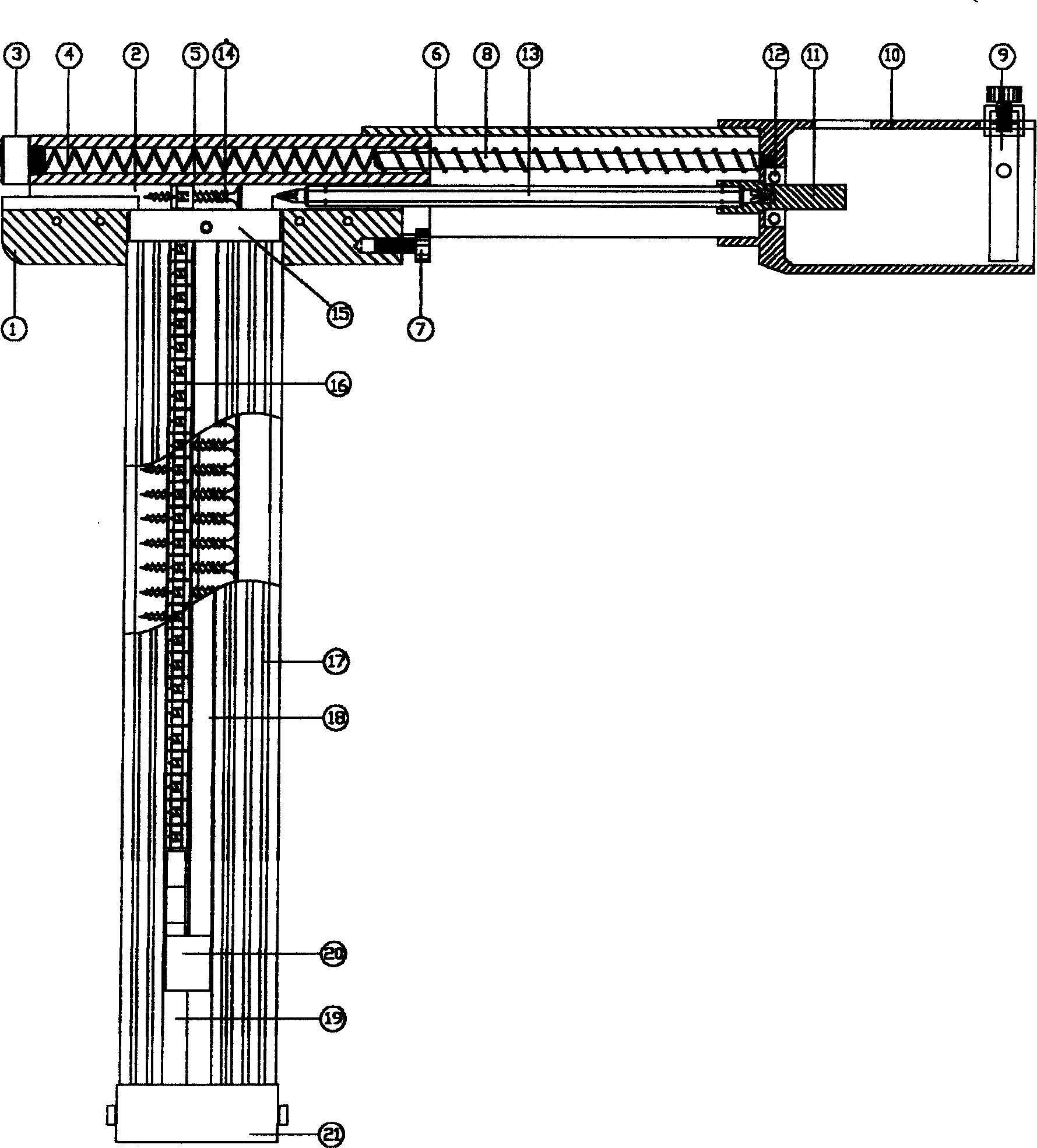
[0011] In the accompanying drawings, the main gun chamber 5 is a semi-circular casing in the shape of an 8, and the material is aluminum alloy, the front screw 3 of the upper hole of the 8 shape, the lower hole of the 8 shape is the main gun bore 2, and the main gun chamber 5 is passed by screws on both sides below. Fixing parts 1 are respectively housed. Rear chamber 6 is inverted U font and is enclosed within the rear portion of main chamber 5 and can slide on main chamber 5, forms a gun body with main chamber 5, and its material is aluminum alloy. Sheath 10 one ends are contained in the rear end of breech chamber 6 by screw, and material is cast aluminum, and spring core 8 is housed in the upper round hole of sheath 10 front ends, and spring core 8 shaft overcoats have spring 4. When the whole gun is installed, the spring 4 and the spring core 8 are packed into the main chamber 5 and the breech chamber 6 top holes. A bearing 12 is housed in the lower circular hole at the f...


PUM


Abstract

The present invention relates to a screw tool for fixing plate material and joint in building decoration. Its discloses an automatic repeating type screw self-mounting gun. It includes bore of gun, and also comprises screw cartrige clip component, and the described bore of gun is divided into main gun bore component and rear gun bore component. Said invention also provides the concrete connection mode of main gun bore, rear gun bore and screw cartridge clip component and its advantages.

Description

technical field [0001] The invention relates to a building decoration tool, in particular to a screw tool for fixing plates and keels in building decoration. Background technique [0002] At present, there are many types of building boards on the market, such as paper-faced gypsum boards, silicon-calcium boards, cement pressure boards, and paperless gypsum boards. When decorating, these boards should be connected with light steel keel or wooden keel with screws, and more than 90% of them are fixed with self-tapping screws. The tool used to fix the screws is an electric drill clip bit, and the screws are fixed one by one by hand. Therefore, the construction intensity is high, the efficiency is low, the precision is poor, and the loss is large, so it is difficult to meet the construction specification requirements. Contents of the invention [0003] Aiming at the defects existing in the prior art, the invention aims to solve the screw tool for fixing plates and keels. The...

Claims


Application Information

Patent Timeline
Patent Type & Authority Applications(China)
IPC IPC(8): B25C1/02
Inventor 束根林盛昭宁
Owner 束根林
Why Eureka
Try Eureka