

Speaker for mobile terminals and manufacturing method thereof
A mobile terminal and loudspeaker technology, applied in the direction of sensors, soil protection, sensor components, etc., can solve problems such as difficulty in generating high-quality sound pressure, damage to speaker efficiency, and low speaker efficiency
- Summary
- Abstract
- Description
- Claims
- Application Information
AI Technical Summary
Problems solved by technology
Method used
Image

Examples
Embodiment Construction
[0046] Hereinafter, embodiments of the present invention will be described in detail with reference to the accompanying drawings.
[0047] To label the drawings, the same reference numerals are used to designate the same or similar parts throughout the different drawings.
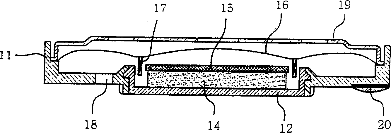
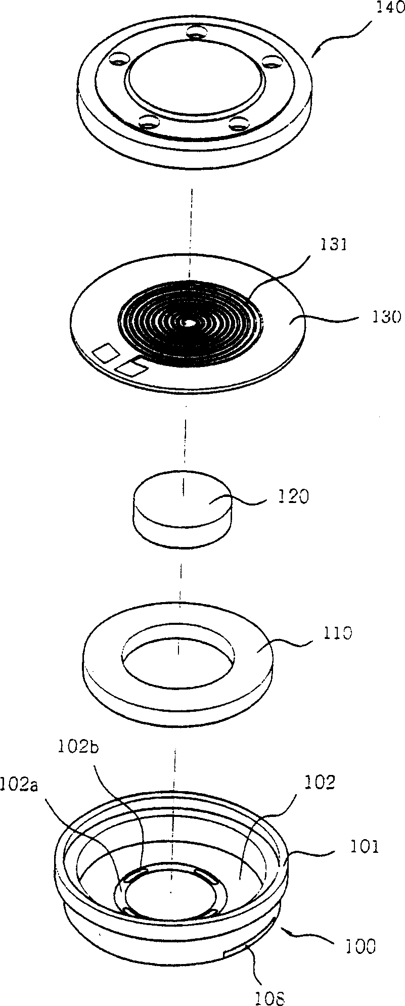
[0048] image 3 is a perspective view of a speaker for a mobile terminal according to a first embodiment of the present invention. Figure 4 yes image 3 Cross-sectional view of the loudspeaker. The following will refer to image 3 and Figure 4 A speaker according to the first embodiment is explained.
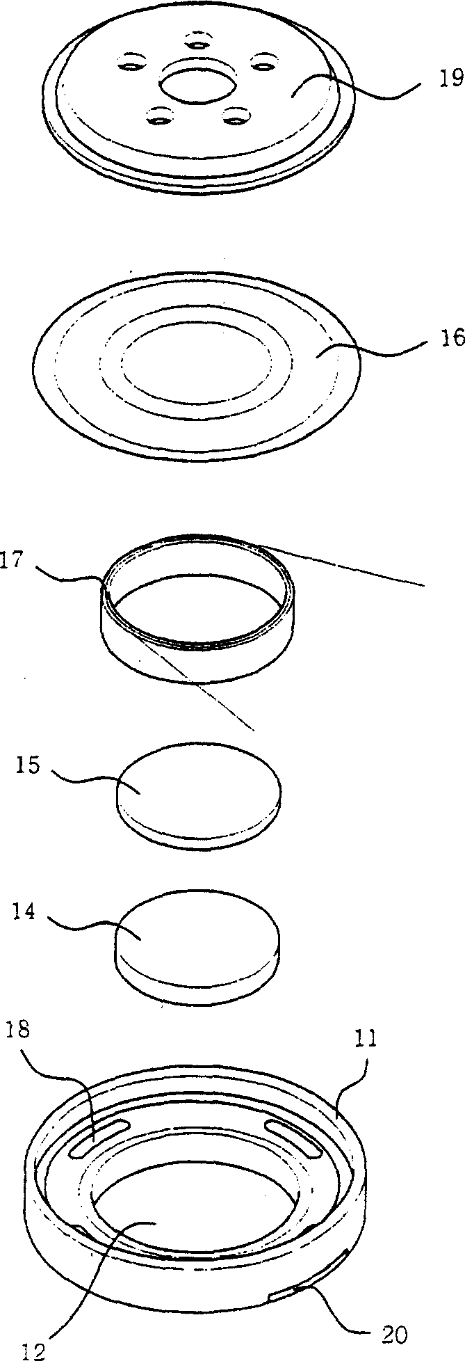
[0049] According to the first embodiment of the present invention, a speaker for a mobile terminal includes: a housing 100 , a support plate 102 , a first magnet 120 , a second magnet 110 , a diaphragm 130 , and a protection plate 140 . The housing 100 forms a space therein with an outer wall 101 extending upward from an outer edge of the housing 100 to a predetermined height. A support plate 102 is ins...
PUM
 Abstract
Description
Claims
Application Information