
Pane display noise-proof structure

A flat-panel display and noise technology, which is applied in the direction of instruments, sound-generating instruments, and instrument cooling, etc., to achieve the effect of convenient appreciation

Inactive Publication Date: 2005-10-05
LG ELECTRONICS(NANJING) PLASMA CO LTD
View PDF0 Cites 5 Cited by
  • Summary
  • Abstract
  • Description
  • Claims
  • Application Information

AI Technical Summary

Problems solved by technology

At the same time, a noise-proof structure is provided to solve the problem of not only achieving the purpose of cooling, but also solving the problem of silencing the noise generated by the cooling system.

Method used


Image

  • Pane display noise-proof structure
  • Pane display noise-proof structure
  • Pane display noise-proof structure

Examples


Embodiment Construction

[0017] A kind of embodiment of the present invention is described below with reference to accompanying drawing:

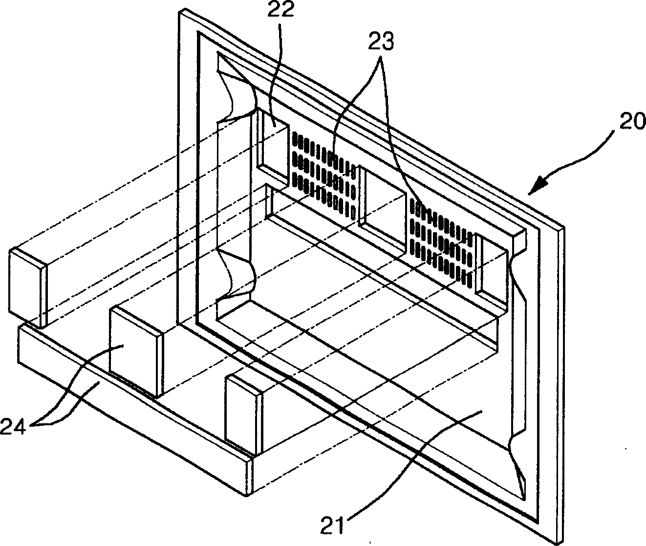
[0018] see image 3 , the figure shows the following parts: PDP 20 generating hot air; rear cover 21 located on the back of the PDP; located above the rear cover, including a plurality of vent holes 23 in a grid-like structure; Recessed installation groove 22; porous sound-absorbing pad placed in the installation groove, etc.

[0019] The structural features are explained in detail below: Considering that the hot gas generated inside the PDP 20 moves upwards, the ventilation hole is opened above the rear cover 21 .

[0020] The above-mentioned installation groove 22 is disposed around the air hole 23 . The mounting grooves are of the same shape, and they can be arranged in a staggered or continuous manner around the air hole 23 . In order to make the sound-absorbing pad 24 be placed in all the installation grooves 22, the installation grooves 22 are made into a ...


PUM


Abstract

The structure comprises following parts: there are vent holes for discharging hot sir on back cover of the panel display. Cooling fan is setup on side of the vent holes at inner side of main body. Mounting groove is arranged around periphery of back cover with vent holes. Noise absorption pad is put inside the mounting groove. The structure makes display cooling effectively and cuts off noise effectively.

Description

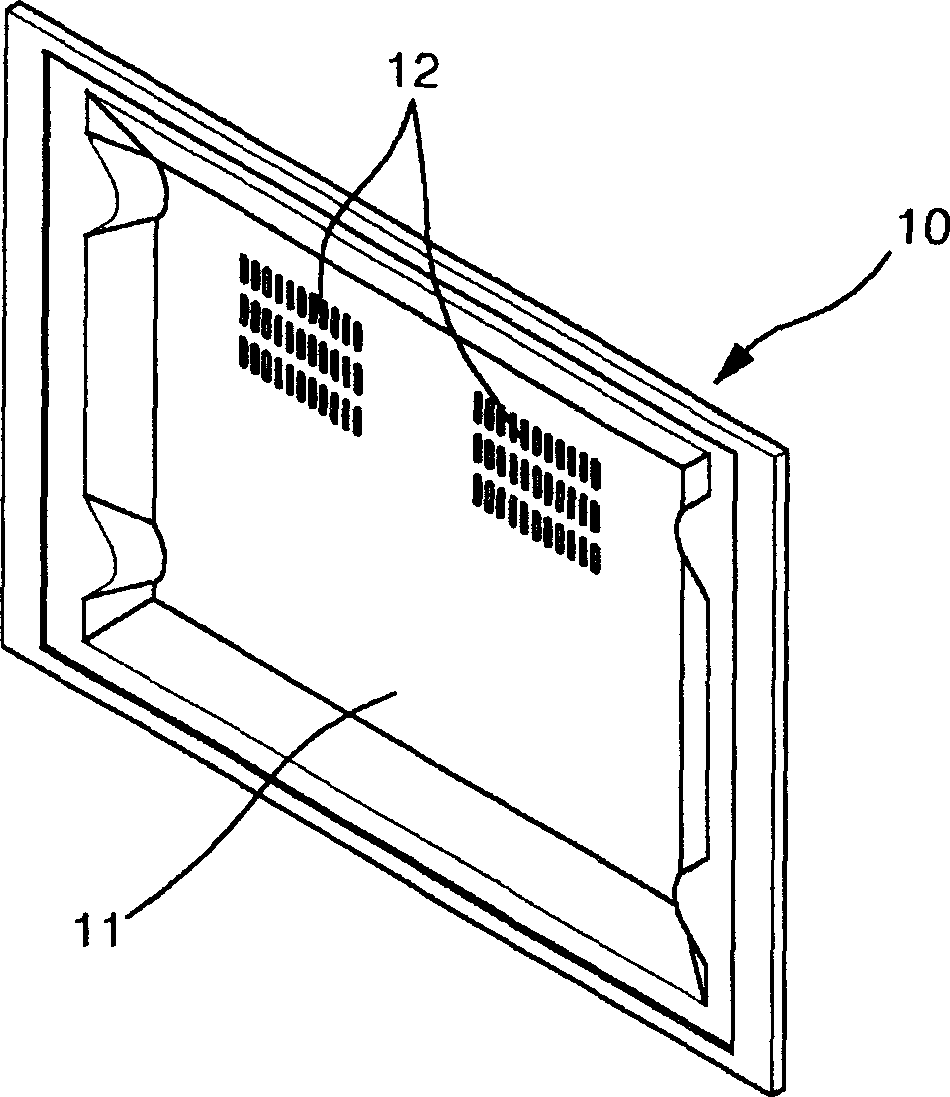
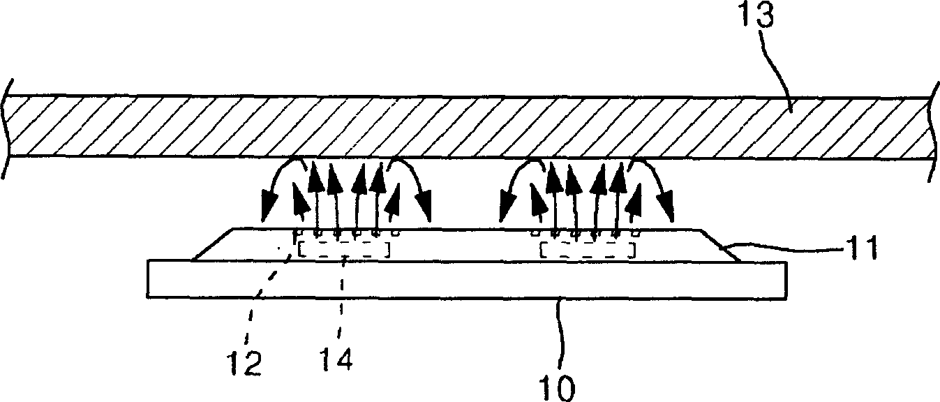
technical field [0001] The invention relates to flat display technology, in particular to a flat display noise prevention structure capable of reducing noise generated in the flat display to the greatest extent. Background technique [0002] Plasma displays (or PDPs) are thin, large screens that can present good-quality images. Due to these advantages, its application range is rapidly expanding, especially in public places. On the other hand, it has become a trend that plasma displays have begun to enter households recently due to lower prices. [0003] However, PDP picture reproduction is realized based on the principle of plasma generation, and the generation of plasma is inevitably accompanied by the generation of a large amount of heat, so it is an important issue to quickly dissipate heat outward. [0004] figure 1 It is to explain the heat dissipation structure of the conventional PDP. see figure 1 The heat dissipation structure of the traditional PDP 10 includes:...

Claims


Application Information

Patent Timeline
Patent Type & Authority Applications(China)
IPC IPC(8): G10K11/162G12B15/04H05K7/20
Inventor 李在基
Owner LG ELECTRONICS(NANJING) PLASMA CO LTD
Learn More