

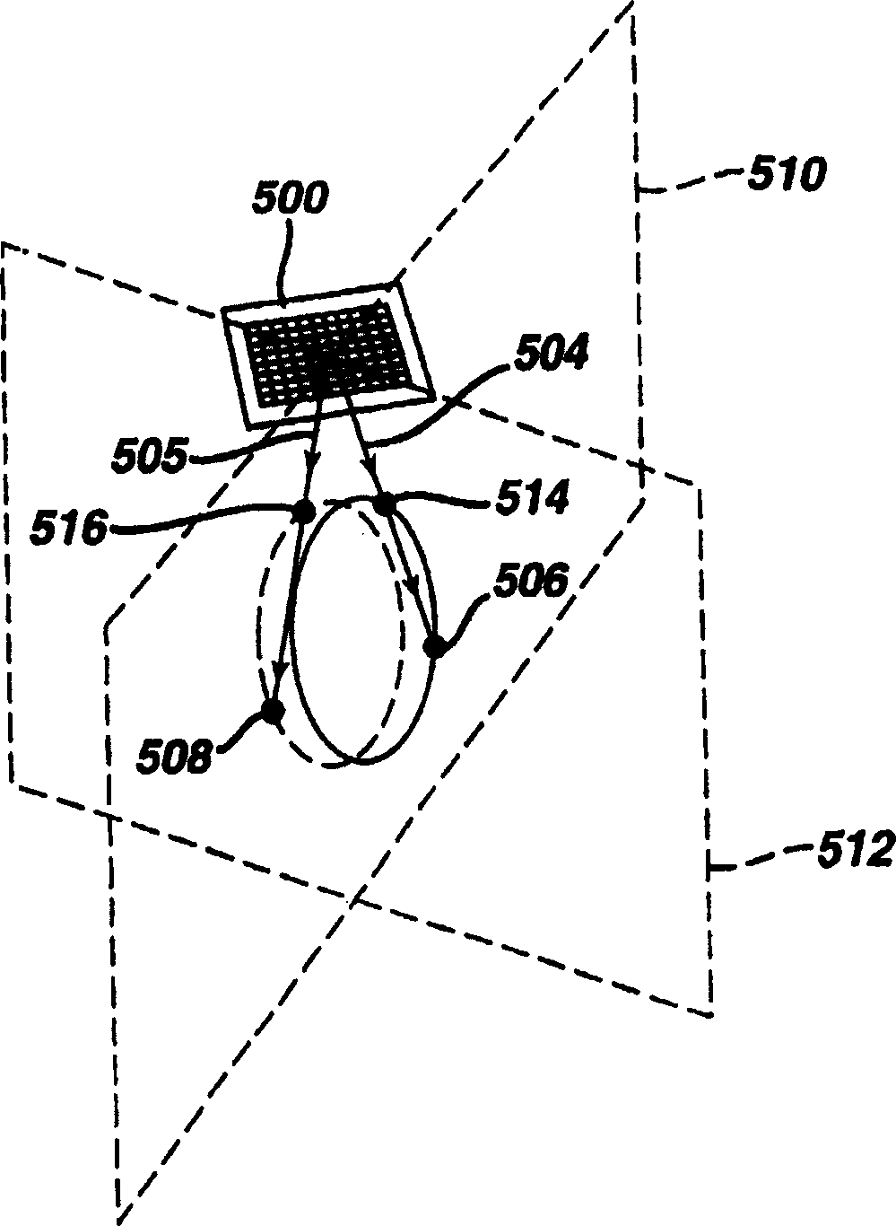
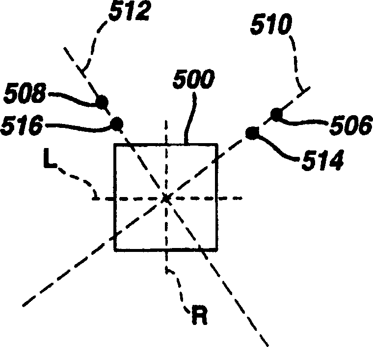
Biplane ultrasonic imaging with icon depicting the mutual plane orientation
A flat, icon-based technology, applied in ultrasonic/sonic/infrasonic diagnosis, application, sound wave diagnosis, etc., can solve the problems that the display technology is not suitable for real-time images, and the display complexity increases
- Summary
- Abstract
- Description
- Claims
- Application Information
AI Technical Summary
Problems solved by technology
Method used
Image

Examples
Embodiment Construction
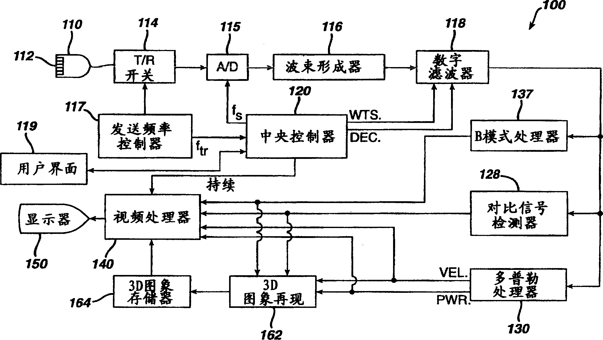
[0016] figure 1 is a block diagram of an ultrasonic diagnostic imaging system 100 applicable to methods and apparatus in accordance with the principles of the present invention. It is to be understood that the present invention is not limited to application only to the imaging system, which is implemented here as an example for illustration. In the imaging system 100, the central controller 120 commands the transmission frequency controller 117 to transmit a desired transmission frequency band. The transmission frequency band parameter ftr is coupled to the transmission frequency controller 117, which causes the transducer 112 of the ultrasound probe 110 to transmit ultrasound in the selected frequency band. Of course, it will be appreciated that any ultrasound frequency or frequency group, referred to as a frequency signal, may be used with due regard to the desired penetration depth and sensitivity of the transducer and ultrasound system.
[0017] Transducer 112 of probe ...
PUM
 Abstract
Description
Claims
Application Information