Clothes dryer

A technology of a clothes dryer and a casing, applied in the field of clothes dryers, can solve the problems of reduced driving motor efficiency, noise generation, overheating of the driving motor, etc.

Inactive Publication Date: 2005-10-12
LG ELECTRONICS INC
View PDF0 Cites 4 Cited by
  • Summary
  • Abstract
  • Description
  • Claims
  • Application Information

AI Technical Summary

Problems solved by technology

[0009] However, in conventional clothes dryers, such as image 3 As shown, when the suction fan rotates, the airflow around the bell mouth 33 changes sharply, so that even if the bell mouth is set on the circumferential surface of the suction hole to guide the airflow smoothly when the air is sucked, the suction of the air Efficiency also drops
Also, noise is generated around this suction hole
[0010] Also, the drive motor used to rotate the suction fan and drum overheats, making the drive motor less efficient

Method used


Image

  • Clothes dryer
  • Clothes dryer
  • Clothes dryer

Examples


Embodiment Construction

[0025] Reference will now be made in detail to the preferred embodiments of the invention, which are shown in the accompanying drawings.

[0026] Examples of embodiments.

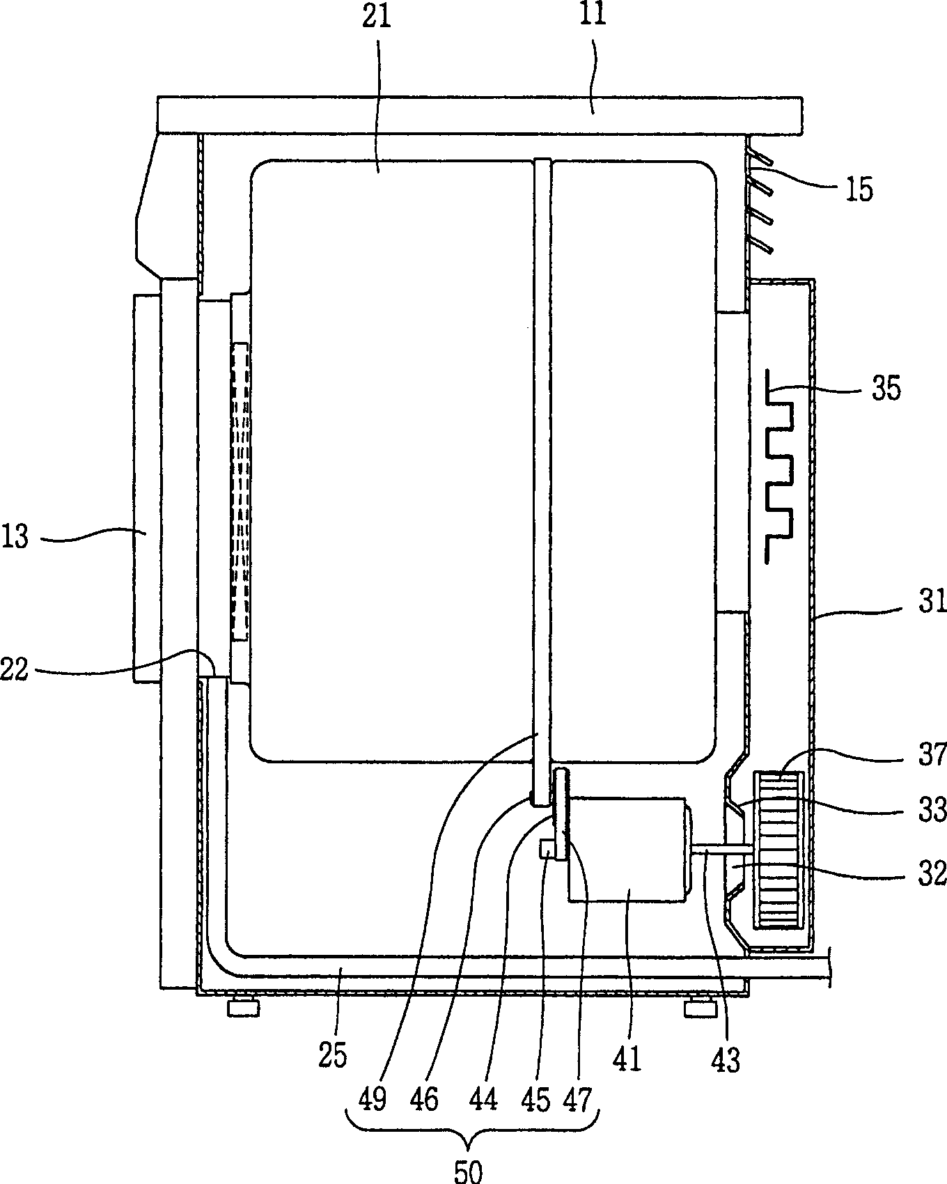
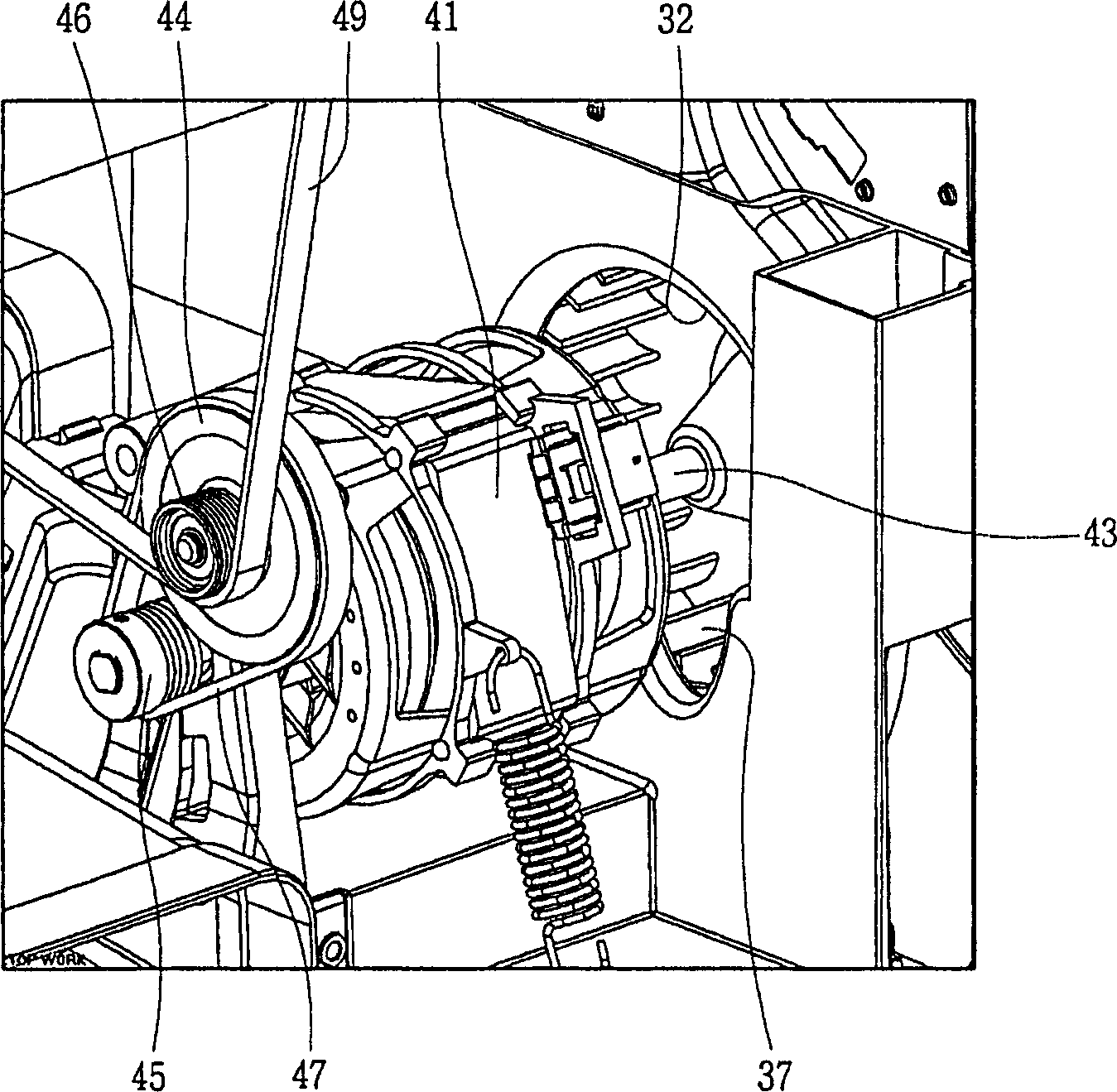
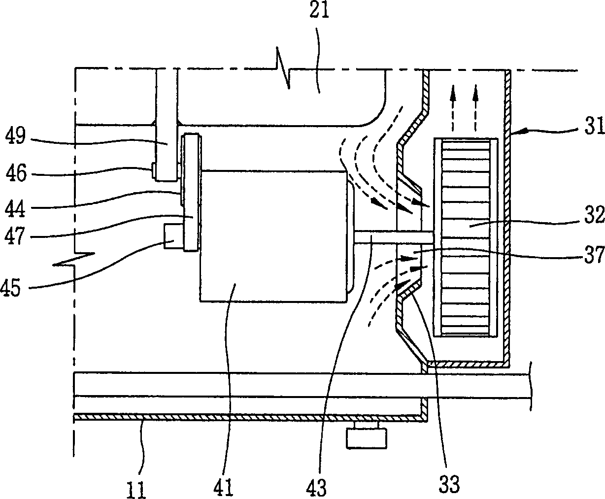
[0027] Figure 4 To illustrate a cross-sectional view according to one embodiment of the invention, Figure 5 for showing Figure 4 Perspective view of the middle suction guide, and Figure 6 for Figure 4 An enlarged view of the main components in .

[0028] As shown in the figure, a clothes dryer according to one embodiment of the present invention includes: a cabinet 80 having a receiving space therein; a drum 90 rotatably installed in the cabinet 80; a suction pipe 95 having Suction hole 95a is used to provide the air in the casing 80 into the drum 90, while the suction pipe is connected to the drum 90 at one side of the drum 90; the suction pipe arranged in the suction pipe 95 The fan 101 is used to suck the air in the housing 80 through the air suction hole 95a; to the air in the suction pipe 9...


PUM


Abstract

Disclosed is a clothes dryer comprising a drum rotatably installed in a cabinet; a suction duct having a suction port for providing air inside the cabinet into the drum, and connected to the drum at one side of the drum; a suction fan arranged in the suction duct, for sucking air inside the cabinet through the suction port; and a suction guide extendingly installed from an outer circumferential surface of the suction port, for guiding air introduced to the suction duct. Thus, as the suction guide is installed at the suction port, it can be achieved to restrain a noise generation due to an air flow, to facilitate to cool a motor and to enhance an energy efficiency.

Description

technical field [0001] The present invention relates to a clothes dryer, and more particularly, to a clothes dryer having a suction guide and capable of limiting noise generated by airflow, facilitating cooling of a motor, and improving energy efficiency. Background technique [0002] figure 1 To show a sectional view of a clothes dryer according to the conventional art, figure 2 for showing figure 1 A perspective view of the air hole in the middle, and image 3 for figure 1 Magnified view of the main section. As shown in the figure, the conventional clothes dryer includes: a cabinet 11 having a receiving space therein; a drum 21 rotatably installed in the cabinet 11; A suction pipe 31 to supply the air to the inside of the drum 21 ; a heater 35 installed in the suction pipe 31 and heating the air; and a driving motor 41 for rotating the drum 21 . [0003] A door 13 is provided on the front surface of the cabinet 11 through which clothes are put into / taken out of the ...

Claims


Application Information

Patent Timeline
Patent Type & Authority Applications(China)
IPC IPC(8): D06F58/02D06F58/04F26B11/02
CPCD06F58/20D06F58/04
Inventor 洪京燮
Owner LG ELECTRONICS INC
Why Eureka
Try Eureka