Light module of light time domain reflector, light time domain reflector and fibre-optical testing method

A technology of optical time domain reflectometer and optical module, which is applied in the direction of optical instrument testing, machine/structural component testing, instruments, etc., can solve the problems of reducing dynamic range, reducing dynamic range, and low utilization rate of test results, etc., to achieve The effect of improving the dynamic range

Active Publication Date: 2005-10-12
HUAWEI TECH CO LTD
View PDF1 Cites 24 Cited by
  • Summary
  • Abstract
  • Description
  • Claims
  • Application Information

AI Technical Summary

Problems solved by technology

[0007] The prior art can be used for OTDR with high dynamic range, but its disadvantage is that the utilization rate of test results is low, which indirectly reduces the dynamic range
[0009] N1 and N2 are different average times, therefore, since the average number of tests is reduced to 1 / 3 of the original, the dynamic range is reduced

Method used


Image

  • Light module of light time domain reflector, light time domain reflector and fibre-optical testing method
  • Light module of light time domain reflector, light time domain reflector and fibre-optical testing method
  • Light module of light time domain reflector, light time domain reflector and fibre-optical testing method

Examples


Embodiment Construction

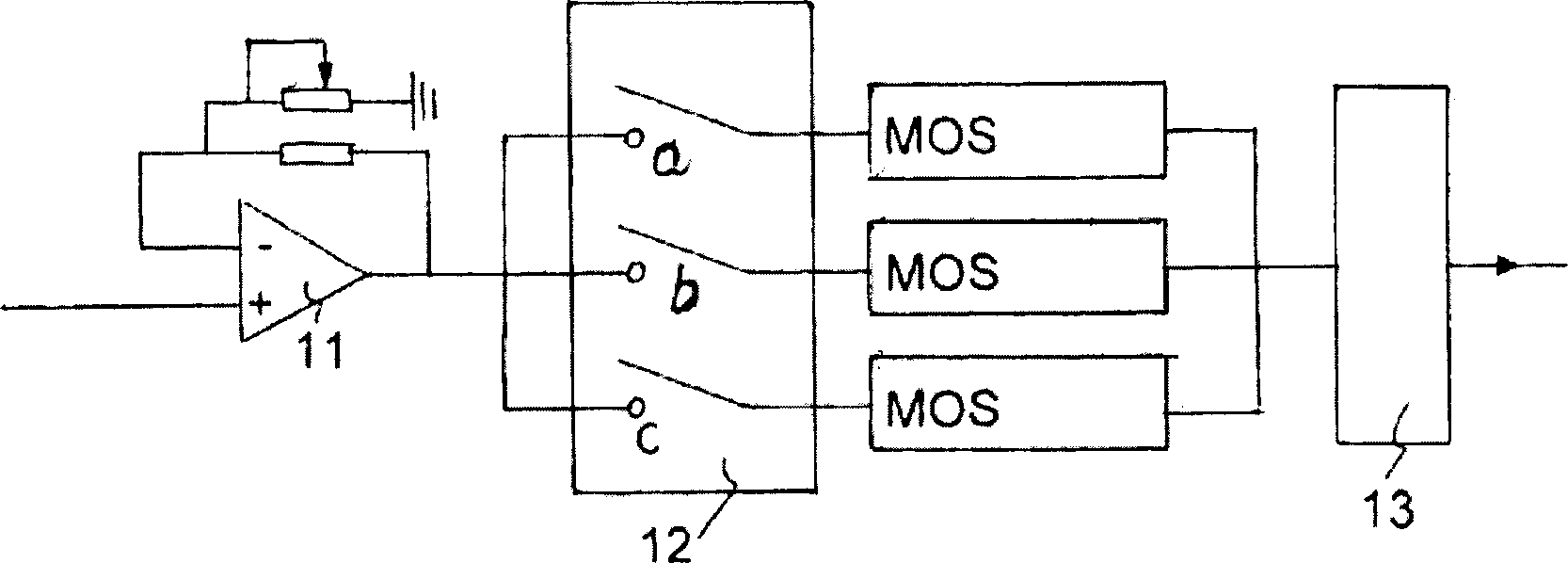
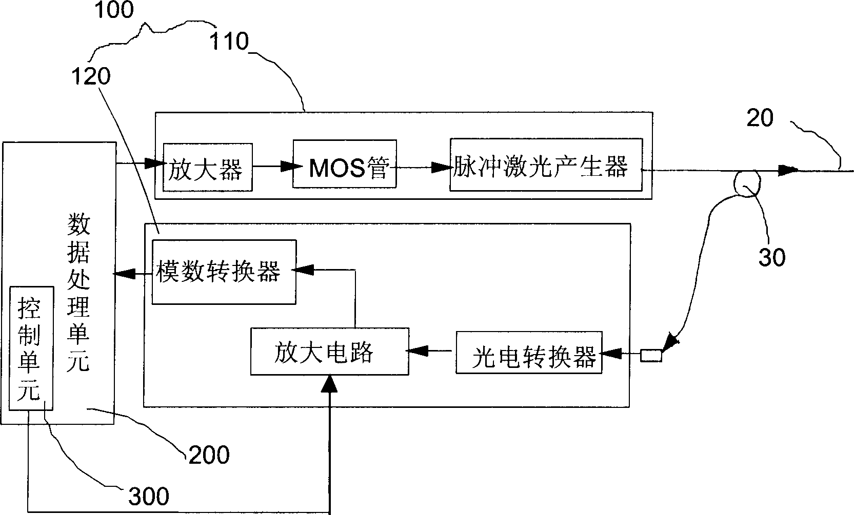
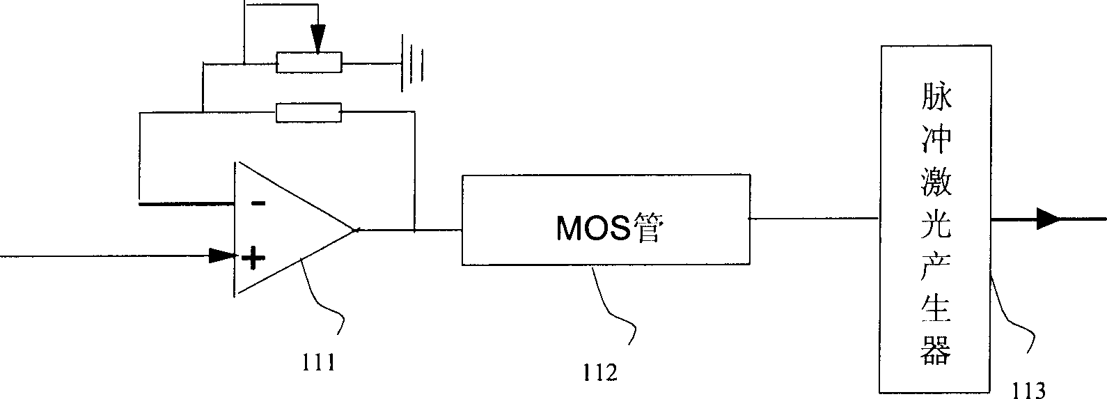
[0038] see figure 2 , is the functional block diagram of the optical time domain reflectometer of the present invention. The optical time domain reflectometer includes an optical module 100, a data processing unit 200 and a control unit 300; wherein the optical module 100 includes a pulse laser 110 for transmitting laser pulses to the optical fiber 20 to be tested through a coupler 30, for The light receiving converter 120 that receives the light signal scattered and reflected back from the optical fiber 20 to be tested through the coupler 30 and converts it into a digital signal; the control unit 300 is used to control the gear switching of the light receiving converter 120; the data The processing unit 200 receives the digital signal output by the light-receiving converter 120 and analyzes the characteristics of the optical fiber 20 to be tested accordingly.

[0039] Generally speaking, since the test pulse width of the optical time domain reflectometer ranges from 10ns to...


PUM


Abstract

The invention consists of pulsed laser and light receiving converter. The pulsed laser is used to emit laser pulse with constant optical power. The light receiving converter comprises optical-electrical converter, amplifying circuit used to amplify the electrical signal above and the A / D converter used to convert the electrical signal into digital signal. The amplifying circuit above comprises at least two amplifying stages and stage switch used to complete segmented amplification of dynamic range.

Description

technical field [0001] The invention relates to optical fiber testing technology, in particular to an optical time domain reflectometer, an optical module thereof and an optical fiber testing method applied to the optical time domain reflectometer. Background technique [0002] With the development of optical fiber communication technology, since the 1980s, the optical fiberization of the network has been one of the main trends in the development of networks in all countries in the world. At present, the composition of communication networks in various countries is mainly based on optical fiber network as the transmission basis. When constructing and maintaining optical cable lines, OTDR (Optical Time Domain Reflectometer, optical time domain reflectometer) must be used to test the characteristics of optical fiber. OTDR is also an optical fiber The core technology in the online monitoring system of the network, the larger the dynamic range, the larger the distance and range ...

Claims


Application Information

Patent Timeline
Patent Type & Authority Applications(China)
IPC IPC(8): G01M11/00H04B10/071
Inventor 廖振钦赵福强
Owner HUAWEI TECH CO LTD
Why Eureka
Try Eureka