Gas turbine pressurizing air supply system

A technology for sealing air and gas turbines, which is applied in the direction of gas turbine devices, cooling of engines, cooling of turbines/propulsion devices, etc., and can solve problems such as power loss of gas turbines

Inactive Publication Date: 2005-10-12
MITSUBISHI HITACHIPOWER SYST LTD
View PDF0 Cites 13 Cited by
  • Summary
  • Abstract
  • Description
  • Claims
  • Application Information

AI Technical Summary

Problems solved by technology

Therefore, the gas turbine loses power again

Method used


Image

  • Gas turbine pressurizing air supply system
  • Gas turbine pressurizing air supply system
  • Gas turbine pressurizing air supply system

Examples


Embodiment Construction

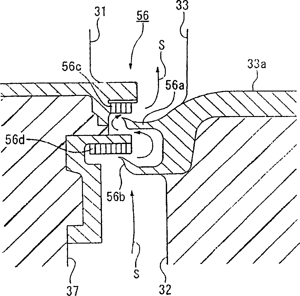
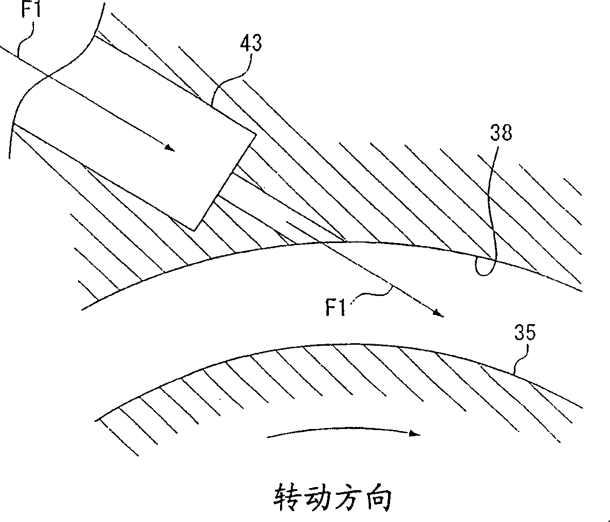
[0023] refer to Figure 1-3 Embodiments of the gas turbine of the present invention will be explained. Of course, the present invention is not limited thereto.

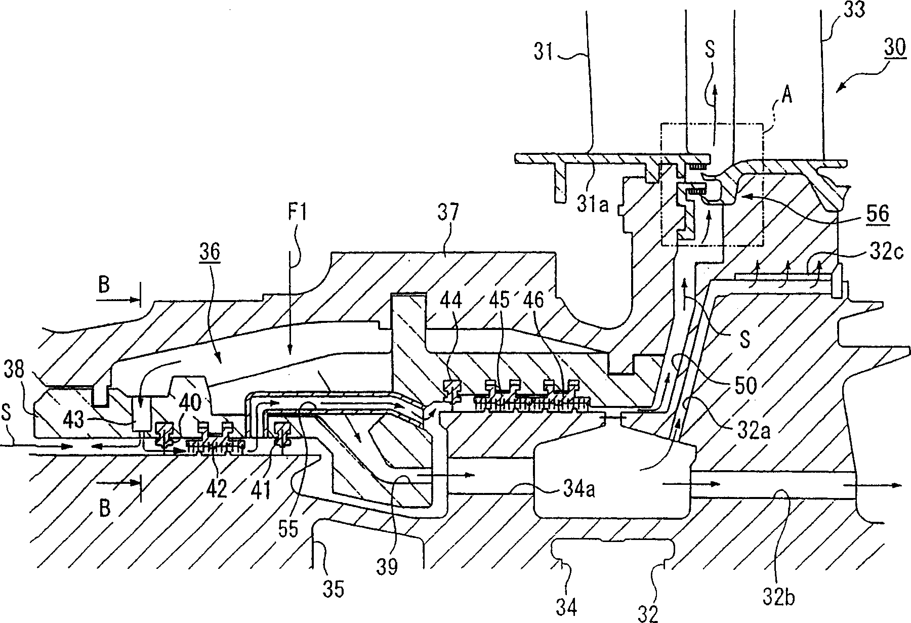
[0024] Note that in the following discussion, the upstream side (i.e. figure 1 The flow direction of the sealing air S and the discharge air F1 on the left side of the paper) is located on the downstream side (ie figure 1 The flow directions of the seal air S and the discharge air F1 on the right side of the paper) are referred to as "upstream side" and "downstream side", respectively. In addition, the direction of the axis of rotation of the rotating member including the sealing disk 34 and the first set of rotor disks 32 ( figure 1 Left and right in ) are referred to as "axial" in the following discussion.

[0025] like figure 1 As shown, the gas turbine of the present invention is provided with a first-stage device 30, which has: first-stage stationary blades 31 (stationary blades), which are arranged on t...


PUM


Abstract

A sealing air bypass flow path is provided in a gas turbine for supplying sealing air to a sealing air supply flow path by bypassing the flow path between each tangential on board injection (TOBI) nozzles and disk holes.

Description

technical field [0001] The present invention relates to a gas turbine driven in rotation using combusted gas from a combustor, and more particularly, to a gas turbine in which gas turbines are driven by tangential on board injection ) nozzle to exhaust the rotor disk to effectively increase the power. Background technique [0002] In gas turbine equipment, compressed air from a compressor is introduced into a combustor, and the gas turbine equipment is driven by high-temperature gas generated when the compressed air is combusted together with fuel introduced into the gas turbine. A typical design is such that part of the compressed air is introduced into the cooling device as exhaust air and cooled. This cooled discharge air is then introduced to the stator blades and the rotor blades on the gas turbine side, and is used as cooling air for these blades and as sealing air between the rotor blades and the rotor blades. [0003] Refer below Figure 4 To explain a design examp...

Claims


Application Information

Patent Timeline
Patent Type & Authority Applications(China)
IPC IPC(8): F01D11/04F01D5/08F01D11/02F01D25/00F02C7/18F02C7/28
CPCF01D11/02F01D5/082F02C7/18
Inventor 由里雅则文森特·劳雷洛羽田哲
Owner MITSUBISHI HITACHIPOWER SYST LTD
Why Eureka
Try Eureka