Hydraulic damper valve based on flow regulation

A technology of flow regulation and hydraulic damping, applied in the field of hydraulic damping valve, which can solve the problem of no automatic damping control function.

Inactive Publication Date: 2005-10-19
JIANGSU UNIV
View PDF2 Cites 9 Cited by
  • Summary
  • Abstract
  • Description
  • Claims
  • Application Information

AI Technical Summary

Problems solved by technology

Such as invention patent 95101934.1, utility model patent 03222544.X, etc., do not have the function of automatic control of damping under high hydraulic conditions

Method used


Image

  • Hydraulic damper valve based on flow regulation

Examples


Embodiment Construction

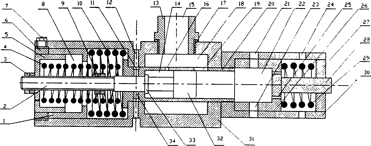
[0019] Such as figure 1 As shown, the present embodiment is formed by combining the features of the above-mentioned technical solutions, which are mainly composed of the main valve body casing (31), the auxiliary valve body casing (30), the flow regulating rod (2), the large piston (1), the small Piston (5), adjusting cylinder (20), primary spring preset nut (3), primary spring (4), secondary spring (10), bottom dead center adjusting nut (9), secondary spring preset nut (6), pressure measuring piston (26), protective spring (29), guide rod (28) and other parts are formed.

[0020] When the pressure oil pumped by the oil pump enters the high-pressure chamber (18) through the oil inlet of the oil pipe joint, enters the overpressure action chamber (22) through the oil inlet hole (19) of the regulating cylinder, and then passes through the normal oil outlet hole (23) of the pressure measuring piston. ) and the normal oil outlet hole (21) of the auxiliary valve body flows out to t...


PUM


Abstract

The damper valve realized on flow regulating principle is key part in automatic hydraulic damping regulation system and is suitable for descending speed control of hydraulic slowly descending chain lift and other similar fields. The damper valve consists of mainly preset nut, flow regulating rod, large piston, small piston, regulating cylinder, main valve body casing, spring and auxiliary valve body casing. It is used in realizing damping in automatic hydraulic damping force controlling system. The damper valve features damping force increased with raised hydraulic pressure, damping force presetting function, capacity of work on high hydraulic pressure condition, and automatic protection function against overload.

Description

technical field [0001] The invention is a hydraulic damping valve based on flow regulation, which is suitable for speed reduction control of hydraulic slow-down chain ladders and other similar application occasions. It can not only realize the automatic control function of hydraulic damping force, but also realize the automatic protection function of large damping when overload occurs. Background technique [0002] In the development process of the hydraulic slow descending chain ladder, a key technology is how to keep the descending speed relatively constant. At present, the method of realization is a hydraulic controller with manual adjustment, a hydraulic controller with electric control, etc. The manually adjusted hydraulic controller cannot realize automatic adjustment. When the load changes, it cannot generate corresponding damping force to keep the speed constant. This solution is not applicable when there is no way to achieve manual intervention. For the electronic...

Claims


Application Information

Patent Timeline
Patent Type & Authority Applications(China)
IPC IPC(8): A62B1/12F16F9/34F16F9/50
Inventor 张荣标周元耀
Owner JIANGSU UNIV
Why Eureka
Try Eureka