Gaming machine

A technology of game consoles and games, which is applied in the field of game consoles and can solve problems such as limited players

Inactive Publication Date: 2005-11-02
UNIVERSAL ENTERTAINMENT CORP
View PDF2 Cites 26 Cited by
  • Summary
  • Abstract
  • Description
  • Claims
  • Application Information

AI Technical Summary

Problems solved by technology

[0005] However, in the video slot machine described above, the timing of changing the symbol display mode is limited to the timing when the game state becomes the winning state of the payout coin, so the timing of attracting players by changing the display mode of symbols is limited.

Method used


Image

  • Gaming machine
  • Gaming machine
  • Gaming machine

Examples


Embodiment Construction

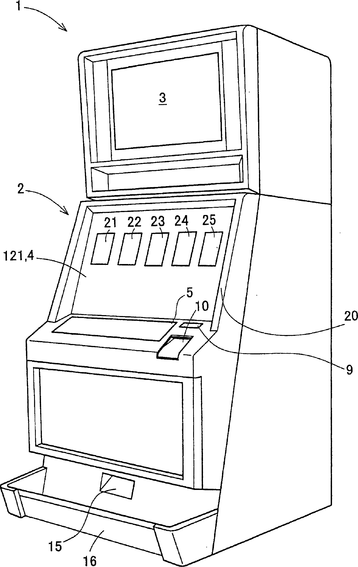
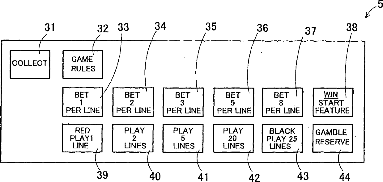
[0062] Next, regarding the gaming machine according to the present invention, an embodiment of a slot machine embodying the present invention will be described in detail with reference to the accompanying drawings. First, the general structure of the slot machine will be described with reference to FIGS. 2 to 4 . Fig. 2 is a perspective view of the slot machine. Fig. 3 is a front view of the control panel. Fig. 4 is a block diagram schematically showing a control system of the slot machine.

[0063] In FIG. 2 , the slot machine 1 has a cabinet 2 forming the overall structure of the slot machine 1 . The upper liquid crystal display 3 is installed at the front upper position of the cabinet 2, and the lower liquid crystal display 4 is installed on the equipment front panel 20, and the front panel 20 is installed at the front middle part of the cabinet 2. Here, both the upper liquid crystal display 3 and the lower liquid crystal display 4 are composed of commonly used liquid cr...


PUM


Abstract

For example, in the variable display portion 21, in a case that the symbol 'LOBSTER' is stopped and displayed on the first stop area 211, the symbol 'J' is stopped and displayed on the second stop area 211 and the symbol 'Q' is stopped and displayed on the third stop area 213, when the player touches the first stop area 211 by the finger 128, the symbol 'LOBSTER' stopped and displayed on the first stop area 211 is displayed so as to spring and the effect sounds representing springing lobster are output.

Description

[0001] This application is based on and claims priority from prior Japanese Patent Application No. 2004-127154 filed on March 22, 2004, the entire contents of which are hereby incorporated by reference. This application is related to a pending US application entitled "GAMING MACHINE", filed on the same date as this application. This co-pending application is hereby incorporated by reference. technical field [0002] The present invention relates to gaming machines in which games are played by using symbols that are variably displayed and then stopped. Background technique [0003] In a conventional gaming machine such as a slot machine, a plurality of reels are rotated for a predetermined time, and coins are paid out corresponding to combinations of symbols displayed when all the reels are stopped. In the case of roughly classifying slot machines based on the type of reels, there are mechanical slot machines (in which a plurality of reels are rotatably provided and symbols ...

Claims


Application Information

Patent Timeline
Patent Type & Authority Applications(China)
IPC IPC(8): A63F5/04G07F17/32G07F17/34
CPCG07F17/3265G07F17/3262G07F17/32G07F17/34
Inventor 稻村幸纪
Owner UNIVERSAL ENTERTAINMENT CORP
Why Eureka
Try Eureka