Antiback component of exhaust duct

An air exhaust duct, anti-backflow technology, applied in vertical pipes, building components, buildings, etc., can solve the problems of affecting the negative pressure effect of the air duct, the flow rate of the air outlet is not ideal, and the growth rate of oil fume and exhaust gas is not ideal.

Inactive Publication Date: 2005-11-09
吴汉木
View PDF2 Cites 3 Cited by
  • Summary
  • Abstract
  • Description
  • Claims
  • Application Information

AI Technical Summary

Problems solved by technology

In the exhaust duct of high-rise residential buildings, on the one hand, the "upper small" air outlet of the cone air channel must have a sufficient cross-section to meet the smooth passage of the high-rise exhaust air volume; on the other hand, the current social demand for the exhaust duct is a small cross-sectional size In this case, the tapered hole is limited by the cross-sectional size of the exhaust duct, and the size of the "bottom is large and the top is small" does not change much. It is necessary to increase the section size of the exhaust duct to make the lower part of the cone hole larger, to make a significant difference between the "lower big and upper small", and to make the air flow through the "lower big upper upper small" cone air flow passage in the air outlet. However, increasing the section size of the exhaust duct is difficult for the market to accept. In this case, the speed of the exhaust gas passing through the air flow channel to the air outlet is not ideal enough to form a relatively large Ideal Negative Pressure Zone
②The air flow in the exhaust duct is at the upper end of the dual transmission parts, and the local vortex is unavoidable, especially when the flow velocity of the air outlet of the air flow channel is not ideal enough to form an ideal negative pressure zone near it, this local vortex It is easy to affect the negative pressure effect of the air induction channel

Method used


Image

  • Antiback component of exhaust duct
  • Antiback component of exhaust duct
  • Antiback component of exhaust duct

Examples


Embodiment Construction

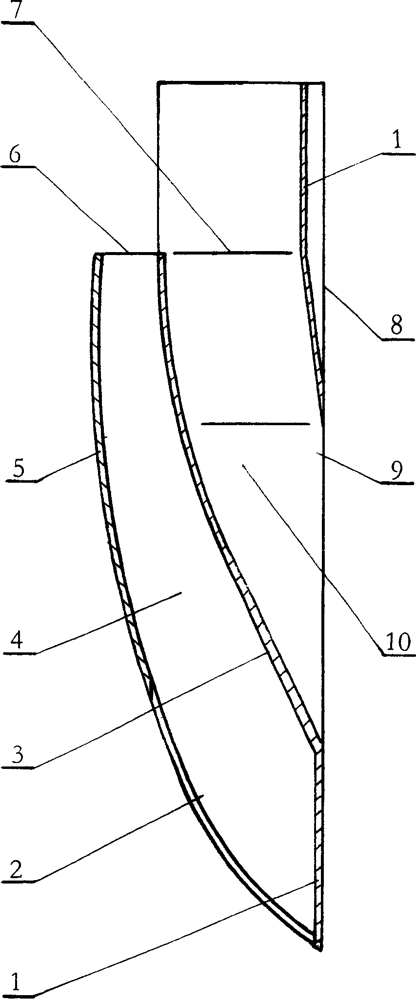
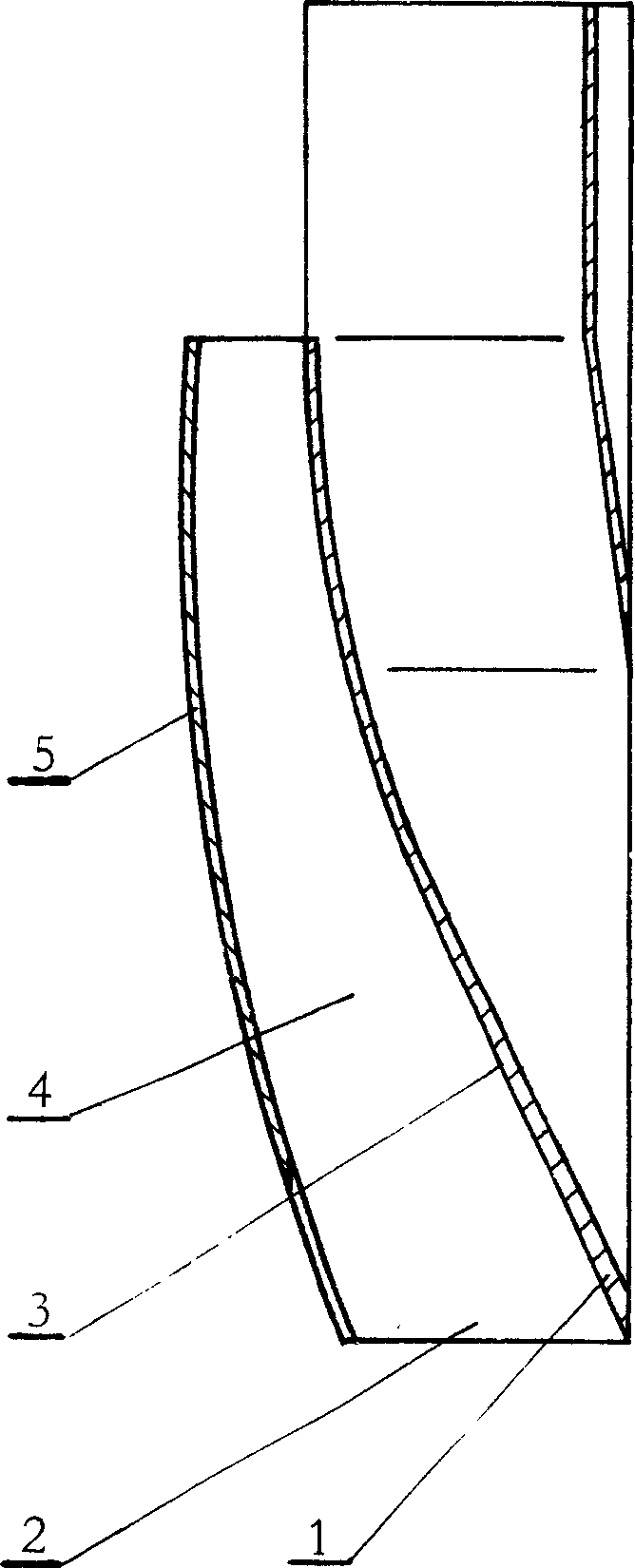
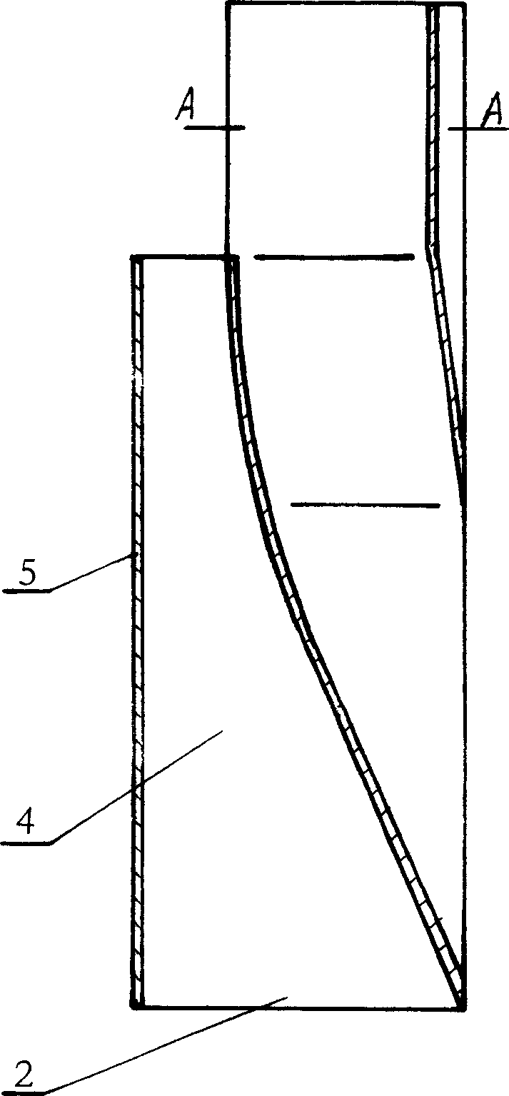
[0017] Such as figure 1 , 2 , 3, 4, 5, and 6, the present invention includes a housing 1 and a speed change plate 5 arranged on the outside of the housing. The external shape of the housing 1 is a cone with a thin bottom and a thick top. The side 8 and the shifting side 3 are provided with an air induction channel 10 in the housing 1, and the shifting plate 5 is a thin plate arranged on the outside of the shifting side 3 of the housing 1, and an inlet is formed between the shifting plate 5 and the shifting side 3. Air outlet 2 is big, and the speed change hole 4 that air outlet 6 is little, housing 1 and speed change plate 5 are packed in the exhaust duct, and the outside of speed change plate 5 is the air passage in the exhaust duct. At the air outlet 6 of the speed change hole 4, the gap between the speed change plate 5 and the speed change side 3 is 10-50m / m. vertical planar sheet or by equation X 2 / A 2 -Y 2 / B 2 =1 hyperbolic thin plate, the speed change plate 5 is ...


PUM


Abstract

The present invention relates to anti-back component of exhaust duct which is used in the exhaust duct of the kitchen or toilet to avoid the reverse irrigate of the oil fume waste gas. The anti-back component includes shell and variable speed plate setting outside the shell, inner the shell there is guiding wind duct which shape is similar to the pot mouth with a bell mouth, there is a variable speed hole which has a big wind inlet and a small wind outlet between the variable speed lateral of the shell and the variable speed plate, the shell and variable speed plate is installed inner the exhaust duct, it is gas stream channel outside the variable speed plate. This anti-back component has simple structure, manufacture and installation is convenient, the effect of exhaust smoke is good, and can insure no reverse irrigation.

Description

Technical field: [0001] The invention relates to an anti-backflow component of the air exhaust duct used in the air exhaust duct of the kitchen and toilet to avoid the oil fume and waste gas in the exhaust duct from flowing backward. Background technique: [0002] Chinese Patent Publication No. CN1514089A discloses a kind of application number is 03126254 exhaust duct dual speed change parts, adopts this technology to realize the various working conditions of kitchen exhaust duct range hoods in small high-rise residential buildings, any use of range hoods without opening The air inlets of the exhaust ducts are all under negative pressure, which has achieved a positive effect that the oil fume and exhaust gas in the exhaust ducts will not flow back into the kitchen where the range hood is disabled. However, when it is used in the exhaust duct of a high-rise residential building, there are still some disadvantages as follows: ① "The shifting side of the double transmission par...

Claims


Application Information

Patent Timeline
Patent Type & Authority Applications(China)
IPC IPC(8): E04F17/04
Inventor 薛生利朱本银李小双李振文吴丽珊吴汉木
Owner 吴汉木
Why Eureka
Try Eureka