Ring oscillator circuit

A technology of ring oscillation circuit and control circuit, which is applied in the direction of electric pulse generator circuit, logic circuit to generate pulse, electrical components, etc., and can solve the problems of incorrect output signal and increase of high harmonic components, etc.

Inactive Publication Date: 2005-11-16
ROHM CO LTD
View PDF1 Cites 2 Cited by
  • Summary
  • Abstract
  • Description
  • Claims
  • Application Information

AI Technical Summary

Problems solved by technology

As a result, the signal of the desired frequency cannot be output correctly, and the high-harmonic component increases, causing adverse effects on unwanted radiation.

Method used


Image

  • Ring oscillator circuit
  • Ring oscillator circuit
  • Ring oscillator circuit

Examples


Embodiment Construction

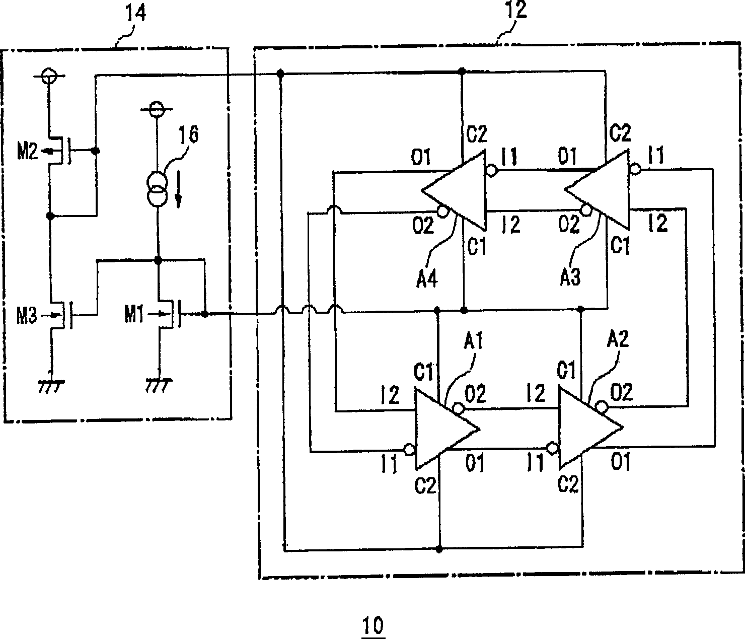
[0019] figure 1 A ring oscillation circuit 10 according to an embodiment is shown. In the figure, an oscillation unit 12 has four differential amplifiers A1 to A4, and oscillates at a predetermined frequency. The control circuit 14 supplies a drive signal to drive the oscillation unit 12 and adjusts the oscillation frequency of the oscillation unit 12 to a desired value.

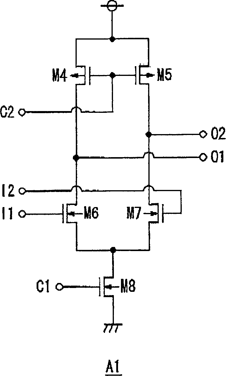
[0020] The differential amplifiers A1 to A4 of the oscillation unit 12 have the same configuration and have terminals for a first input I1 and a second input I2, a first output O1 and a second output O2, and a first control signal C1 and a second control signal C2. In addition, there are terminals for a power supply VDD and a ground GND which are not shown. The four differential amplifiers A1 to A4 are wired in a ring shape, and each of the first output O1 and the second output O2 is connected to the first input I1 and the second input I2 of the next differential amplifier. Among them, in order to contin...


PUM


Abstract

A turn-round is provided in the middle of a plurality of differential amplifiers A 1 -A 4 . A first-stage differential amplifier A 1 is provided in close proximity to a final-stage differential amplifier A 4 so that distances between adjacent differential amplifiers are substantially equal to each other. With this, signal lines between the differential amplifiers are uniform in length and propagation delays are uniform. As a result, a high single-frequency oscillation signal is output.

Description

technical field [0001] The present invention relates to a ring oscillation circuit, in particular to a ring oscillation circuit with a plurality of inverting amplifiers. Background technique [0002] In order to obtain a signal oscillating at a desired frequency, it is known to arrange a plurality of inverters in series, and return the output of the final stage to the primary ring oscillation circuit. Figure 8 Shows the structure of a general ring oscillation circuit. Here, five inverters INV1 to 5 are arranged in series, and the output of the last-stage inverter INV5 is returned to and input to the first-stage inverter INV1. In this example, since there is an odd number of inverters, the oscillation operation continues. Such a ring oscillation circuit is also disclosed in Patent Document 1, for example. [0003] Patent Document 1: (Japanese) Unexamined Patent Publication No. 2001-85994 (full text) [0004] However, if Figure 8 Or in the arrangement as in Patent Documen...

Claims


Application Information

Patent Timeline
Patent Type & Authority Applications(China)
IPC IPC(8): H03K3/354H03K3/0231H03K3/03
CPCH03K3/0322
Inventor 胁井刚
Owner ROHM CO LTD
Why Eureka
Try Eureka