

Steam engine
A technology of engine and steam, applied in the direction of steam engine device, machine/engine, mechanical equipment, etc., can solve the problem of large heat loss and so on
Inactive Publication Date: 2005-11-23
DENSO CORP
View PDF1 Cites 2 Cited by
- Summary
- Abstract
- Description
- Claims
- Application Information
AI Technical Summary
Problems solved by technology
Therefore, this type of steam engine has a greater heat loss
Method used
View moreImage
Smart ImageViewing Examples

Examples
no. 1 approach
no. 2 approach
no. 3 approach
Login to View More PUM
 Abstract
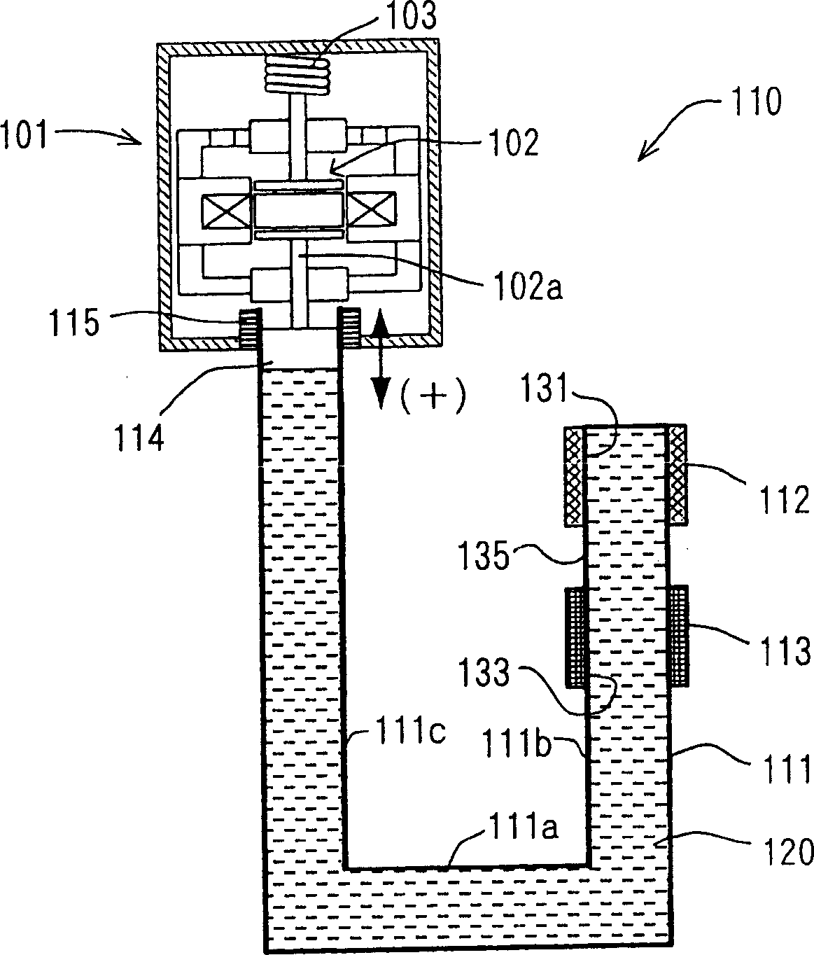
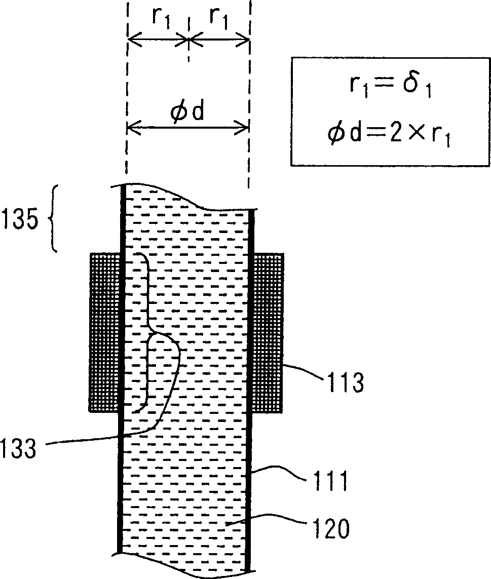
A steam engine has a pipe shaped fluid container, a heating and cooling devices respectively provided at a heating and cooling portions of the fluid container, and an output device connected to the fluid container, so that the output device is operated by the fluid pressure change in the fluid container, to generate an electric power. In such a steam engine, an inner radius 'r 1' of the cooling portion is made to almost equal to a depth 'delta 1' of thermal penetration, which is calculated by the following formula (1).
Description
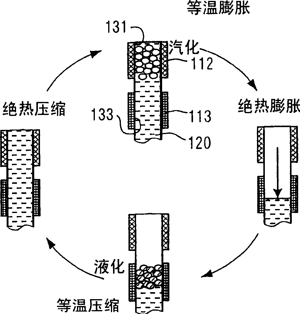
technical field The present invention relates to a steam engine having a liquid container filled with a working liquid, and vibrating the working liquid in the liquid container in a self-excited vibration through repeated operations of vaporizing and liquefying the working liquid by heating and cooling the working liquid. Mechanical energy is generated at the output of the steam engine by vibratory operation of the liquid in a liquid container. Background technique Those skilled in the art are already familiar with equipment for steam engines, for example, the published application in Japanese Patent Laid-Open Application No: S58-057014, wherein the working liquid is filled in a liquid container, the working liquid is heated and vaporized by a heating device, and The working liquid is cooled and liquefied by the cooling device, and energy is obtained through repeated vaporization and liquefaction of the working liquid. That is, the output device in the above-mentioned ste...
Claims
Login to View More Application Information
Patent Timeline
 Patent Type & AuthorityApplications(China)
IPC IPC(8): F01K21/02F01B29/00F01K25/04
Inventor八束真一小田修三萩原康正森下敏之小牧克哉
OwnerDENSO CORP