High power LED package

A LED packaging, high-power technology, applied in semiconductor devices, electrical components, circuits, etc., can solve problems such as low thermal conductivity, insignificant heat dissipation performance, and reduced LED luminous performance.

Inactive Publication Date: 2005-12-14
LG ELECTRONICS INC
View PDF0 Cites 26 Cited by
  • Summary
  • Abstract
  • Description
  • Claims
  • Application Information

AI Technical Summary

Problems solved by technology

[0010] In the above-mentioned LED package, the heat generated during LED operation is not directly transferred to the aluminum heat sink 211 with excellent heat dissipation performance on the surface, but is transferred to the aluminum heat sink 211 through the plastic body 205 and PCB 210 with low thermal conductivity In this way, the heat dissipation efficiency is reduced, resulting in the reduction of LED luminous performance
[0011] In particular, although a greater amount of heat is generated in the operation of high-power LEDs applied to backlight units of LCDs and general lighting equipment, LEDs show insignificant heat dissipation performance, thus further reducing the luminous performance of LEDs

Method used


Image

  • High power LED package
  • High power LED package
  • High power LED package

Examples


no. 1 example

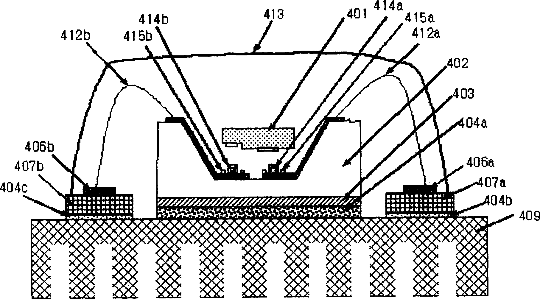
[0031] According to the first embodiment, the high-power LED package includes LED401, silicon base 402, insulating layer 403, adhesive 404a, metal lines 406a and 406b, insulating substrates 407a and 407b, heat sink 409, wires 412a and 412b, lens 413 , solder 414a and 414b, and solder dams 415a and 415b.

[0032] In this high power LED package, a silicon base 402 with a flip-chip bonded LED 401 is directly attached to the upper surface of a heat sink 409 using an adhesive 404a. Thus, the adhesive 404a includes a material having excellent thermal conductivity and a similar thermal expansion coefficient to the base 402, examples of which are aluminum paste and silver paste. Further, the heat sink 409 can be made of conductor or non-conductor.

[0033] refer to image 3 , the silicon base 402 has a groove to accommodate the LED 401 therein. The grooves of the base 402 are formed by subjecting a silicon wafer mainly used for manufacturing the base to wet etching using a potassiu...


PUM


Abstract

The invention discloses a high-power LED package, including LED; a silicon base for flip-chip bonding of the LED; a reflective film formed on the silicon base and electrically connected to the LED; wires connected to the reflective film; and an insulator formed under the silicon base ; a heat sink formed under the insulator; an insulating substrate formed on the heat sink; and a metal wiring formed on the insulating substrate and connected to an electric wire. In this LED package, the silicon base is directly connected to the heat sink, and the heat generated when the LED is in operation is effectively dissipated. High-power LEDs can be applied to LCD backlight units or general lighting equipment, and can also be applied to traditional PCS phone backlight units or LED devices of key bases, which improves the light characteristics of LEDs. In particular, the LED package has a simple structure and has two or more arrays each having a base on which the LED is flip-chip bonded, so it can be applied to a backlight unit module of an LCD, greatly reducing manufacturing costs.

Description

technical field [0001] The present invention relates generally to high-power LED packages, and more particularly, to a package structure that effectively dissipates heat generated during LED operation. Background technique [0002] LEDs (Light Emitting Diodes), which have advantages in that they show energy saving effects superior to conventional light sources and can be used semi-permanently, are attracting attention as next-generation light sources at a time when optical semiconductors lead compound semiconductors into the 21st century. Currently, since the brightness problem of LEDs is greatly improved, LEDs are widely used in all industrial fields, including backlight units, automobiles, electric signals, traffic lights, lighting devices, and the like. [0003] In particular, LEDs having a small size and high luminance used in backlight units replace CCFL lamps used as light sources of conventional backlight units, and therefore, it is conceivable that the production num...

Claims


Application Information

Patent Timeline
Patent Type & Authority Applications(China)
IPC IPC(8): H01L33/46H01L33/58H01L33/60H01L33/62H01L33/64
CPCH01L33/62H01L33/642H01L2224/48091H01L2224/73265H01L2924/10253H01L2924/3011H01L2924/00014H01L2924/00
Inventor 金根浩朴七根宋基彰
Owner LG ELECTRONICS INC
Why Eureka
Try Eureka