Silencer of closed compressor

A hermetic compressor and muffler technology, applied in the field of compressor devices, can solve the problems of reduced productivity and increased cost, and achieve the effects of improving productivity, reducing noise and saving costs

Inactive Publication Date: 2005-12-28
LG ELECTRONICS (TIANJIN) APPLIANCES CO LTD
View PDF0 Cites 11 Cited by
  • Summary
  • Abstract
  • Description
  • Claims
  • Application Information

AI Technical Summary

Problems solved by technology

[0015] As mentioned above, although the conventional hermetic compressor muffler (9) has an auxiliary muffler (12) inside and has the effect of reducing noise, the component

Method used


Image

  • Silencer of closed compressor
  • Silencer of closed compressor
  • Silencer of closed compressor

Examples


Example Embodiment

[0038] Hereinafter, the present invention will be described in detail with reference to the drawings and embodiments.

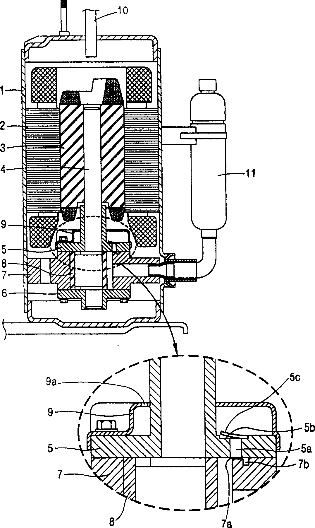
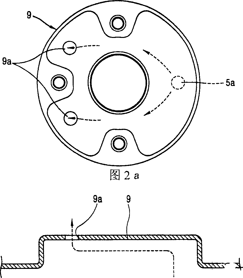
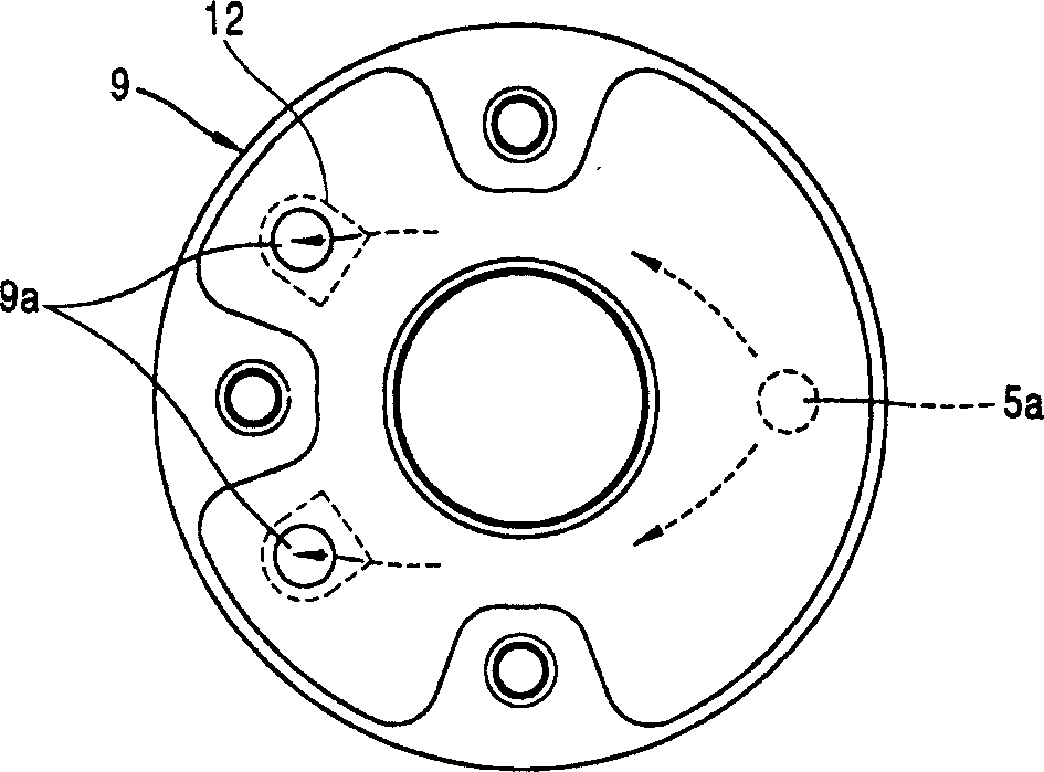
[0039] Figure 4 It is a schematic diagram of the longitudinal cross-sectional structure of a hermetic compressor equipped with a muffler of the present invention. Figure 5 Is a schematic diagram of the appearance structure of the present invention, Figure 6a It is a schematic top view of the cold gas discharged from the muffler of the present invention, Figure 6b It is a schematic front view of the cold gas discharged from the muffler of the present invention, Figure 7 It is a schematic diagram of the appearance structure of another embodiment of the present invention.

[0040] In the description of the present invention, in order to highlight the gist of the present invention, detailed descriptions of well-known functions or configurations are omitted.

[0041] In addition, the same or similar parts with the above-mentioned configuration are designated with...


PUM


Abstract

The invention includes a chassis having certain internal space, a motor part generating rotation force in the chassis, a rotator connected with the motor part, a certain volume resonant in an enclosed compressor having a narrow part communicated with a wide part, a gas discharge hole discharging the refrigeration gas into the chassis via the resonant and an auxiliary silencer having communication opening part of the gas discharge hole.

Description

technical field [0001] The invention relates to a device for a compressor, in particular to a muffler for a hermetic compressor. Background technique [0002] In general, compressors are classified as closed type or separate type in the form of an arrangement of a motor mechanism part and a compression mechanism part. Among them, the hermetic compressor is inside a closed casing, and has a motor mechanism part and a compression mechanism part at the same time, and constitutes a core component of a household appliance using a refrigeration cycle system, such as an air conditioner or a refrigerator. [0003] figure 1 Fig. 2a is a schematic diagram of the longitudinal section structure of the conventional hermetic compressor, and Fig. 2a is a schematic top view of the refrigerant gas discharged from the muffler of the conventional hermetic compressor. Figure 2b It is a schematic diagram of the front view of the refrigerant gas discharged from the muffler of the conventional ...

Claims


Application Information

Patent Timeline
IPC IPC(8): F04C29/06
Inventor 廉容范
Owner LG ELECTRONICS (TIANJIN) APPLIANCES CO LTD
Why Eureka
Try Eureka