LED lamp and lamp reflector assembly

A technology of LED lamps and reflectors, which can be used in vehicle parts, transportation and packaging, lighting and heating equipment, etc., and can solve the problems of increasing installation costs

Active Publication Date: 2005-12-28
OSRAM SYLVANIA INC
View PDF0 Cites 6 Cited by
  • Summary
  • Abstract
  • Description
  • Claims
  • Application Information

AI Technical Summary

Problems solved by technology

However, these LED sources are hardwired into their

Method used


Image

  • LED lamp and lamp reflector assembly
  • LED lamp and lamp reflector assembly
  • LED lamp and lamp reflector assembly

Examples


Embodiment Construction

[0013] For a better understanding of the present invention and its other and further objects, advantages and capabilities, reference is made to the following description and appended claims taken in conjunction with the accompanying drawings.

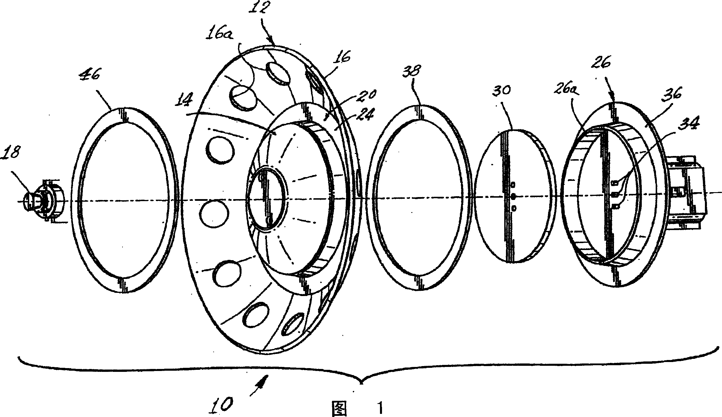
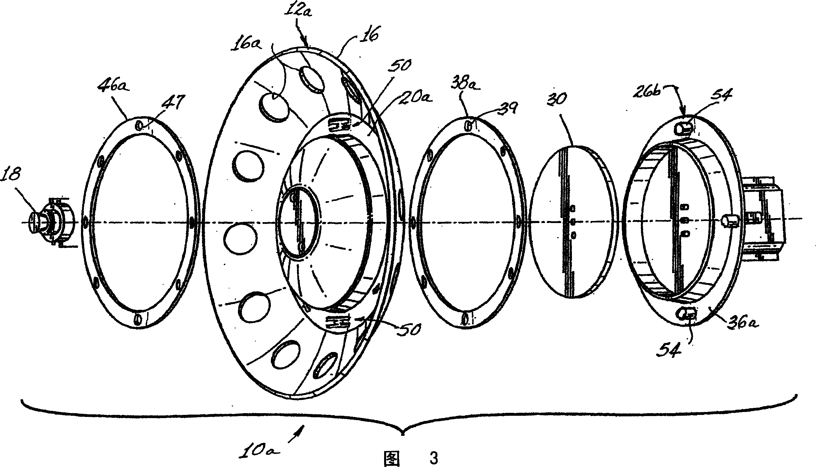
[0014] Referring now to FIG. 1 , there is shown an LED lamp 10 having a generally concave heat sink 12 with a raised frusto-conical central portion 14 surrounded by an outer edge 16 . The fins 12 are preferably formed of aluminum or other metal, and at least the frusto-conical central portion preferably has a reflective coating, for reasons that will become more apparent below. To further aid in heat dissipation, the outer edge 16 may be provided with a plurality of openings 16a.

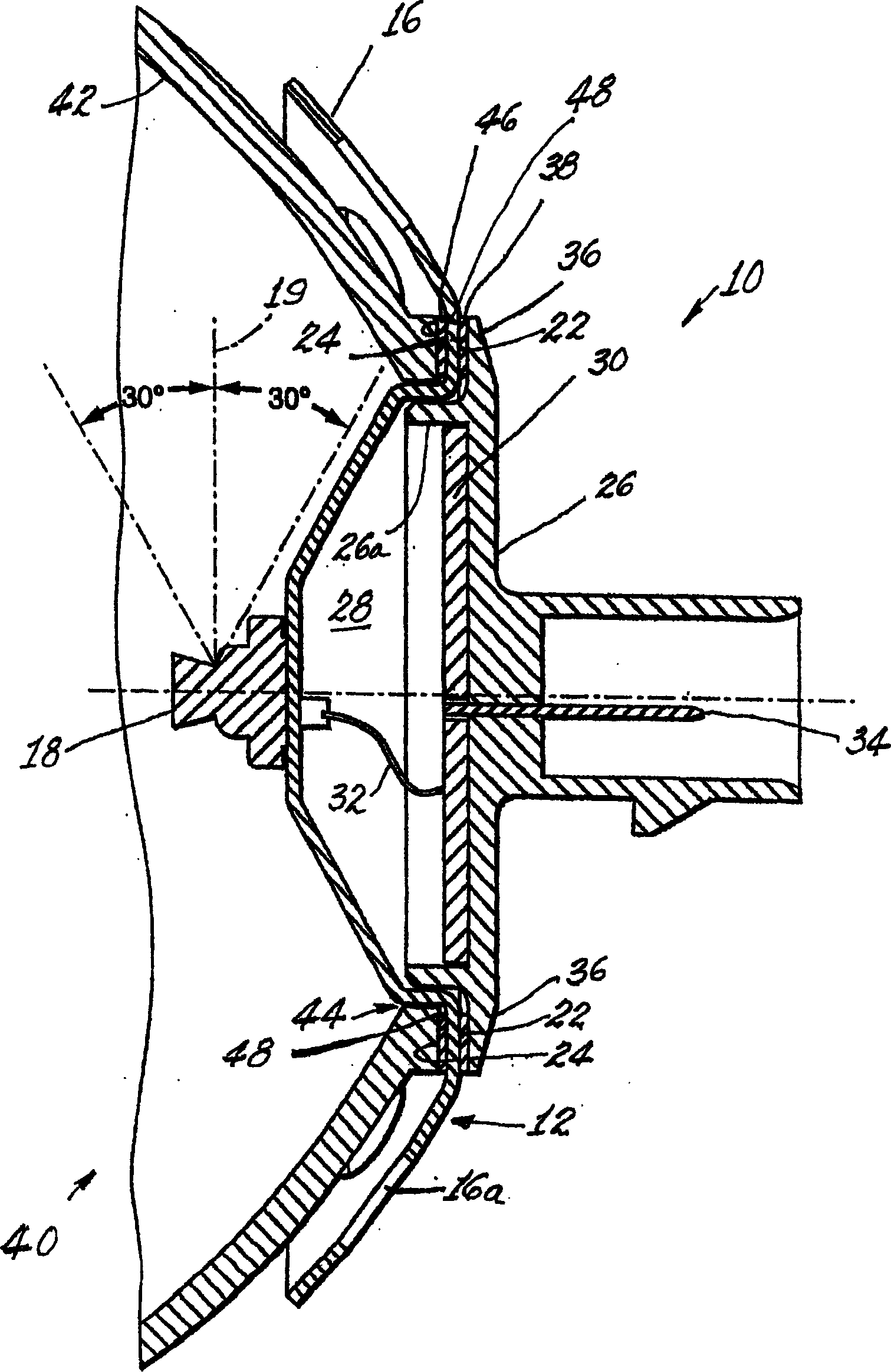
[0015] Side-emitting LEDs 18 are mounted on the frusto-conical central portion 14 . In a preferred embodiment, the side emitting LED will have a vertical axis 19 (see figure 2 ) leaves the distribution of 60°±30°. A peripheral flat region 20 is formed betw...


PUM


Abstract

An LED lamp has a generally concave fin (12) with a raised frusto-conical central portion (14) surrounded by an outer edge (16). The fins (12) are preferably aluminum or other metal and at least the frusto-conical central portion preferably has a reflective coating. To further aid in heat dissipation, the outer edge (16) may be provided with a plurality of openings (16a). A cover (26) is secured to the outer surface (22) and defines a volume (28) between the frusto-conical central portion (14) and the cover (26). An electrical circuit (30) is located within the volume (28), and an electrical connection (32) provides connection to the LED (18). In another embodiment, the cover (26a) is provided with a latch (54) and the reflector (42a) is provided with a latch (56) that engages a barb (50) formed in the heat sink (12a).

Description

technical field [0001] The present invention relates to electric lamps, and in particular to electric lamps having light emitting diode (hereinafter LED) light sources. More particularly, the present invention relates to an electric lamp in which the LED light source is connected to the heat sink by a snap-fit ​​structure. Background technique [0002] In the past, most vehicle light sources involved the use of incandescent bulb bodies. While operating well and at low cost, these bulbs have a relatively short life, and of course the thin filaments employed are always susceptible to damage due to vibrations. [0003] In recent years, certain applications in particular for parking lights have been replaced by LEDs. These solid state light sources have incredible lifetimes in the range of 100,000 hours and are not prone to vibration failures. However, these LED sources are hardwired into their proper locations, which increases installation costs. It would therefore be an ad...

Claims


Application Information

Patent Timeline
IPC IPC(8): F21S8/10
CPCF21S43/14F21S45/10F21S45/47F21S45/48
Inventor C·M·库谢恩M·塔克T·特斯诺
Owner OSRAM SYLVANIA INC
Why Eureka
Try Eureka