Method for supporting and incorporating bearing, protective cover and reprocessing method

A protective cover and reprocessing technology, applied in the direction of shafts and bearings, supporting machines, bearing components, etc., can solve problems such as difficult to obtain slip rings, difficult to achieve, etc., to achieve the effect of reducing danger and excellent sealing

Inactive Publication Date: 2006-09-27
AB SKF
View PDF2 Cites 1 Cited by
  • Summary
  • Abstract
  • Description
  • Claims
  • Application Information

AI Technical Summary

Problems solved by technology

[0004] The invention relates more particularly to the manufacture of rotors, in which the difficulty exists of obtaining slip rings whose outer surface is well concentric with the rotor shaft, without damaging other parts located nearby difficult to achieve

Method used


Image

  • Method for supporting and incorporating bearing, protective cover and reprocessing method
  • Method for supporting and incorporating bearing, protective cover and reprocessing method
  • Method for supporting and incorporating bearing, protective cover and reprocessing method

Examples


Embodiment Construction

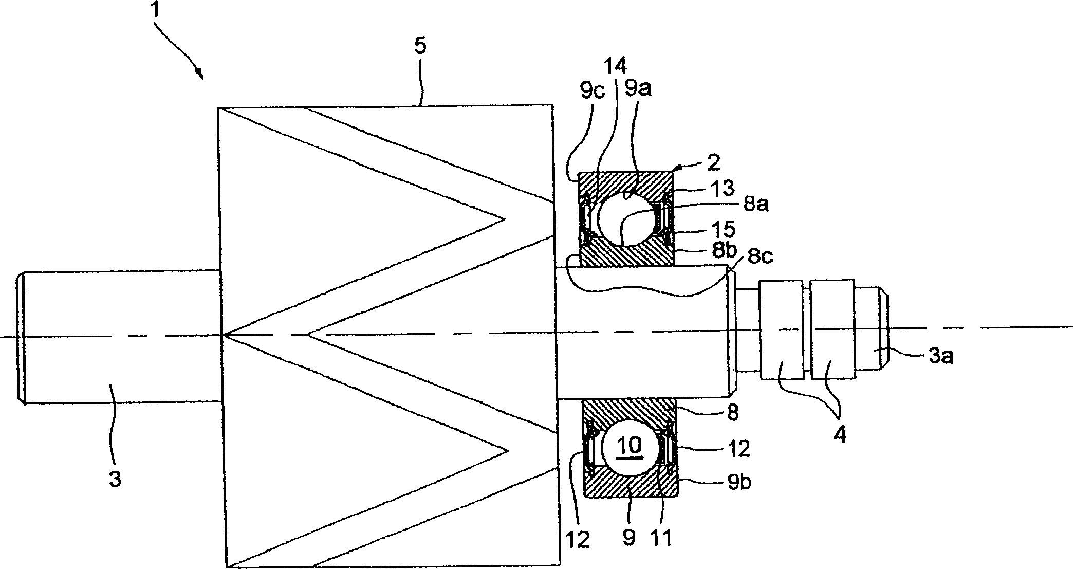
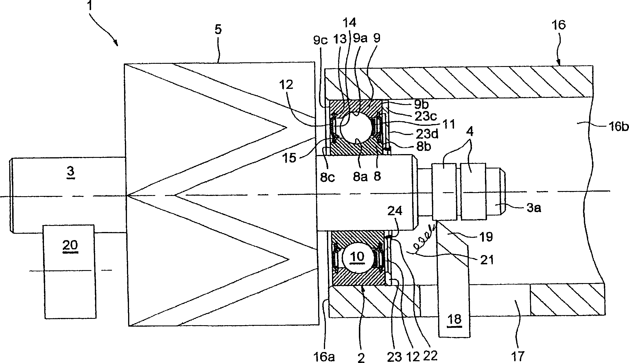
[0037] from figure 1 It can be seen that the rotor 1 is combined with the bearing 2. The rotor 1 includes a shaft 3 having a small-diameter end 3 a that supports a slip ring 4 . The rotor 1 also comprises a body 5 comprising pole pieces and windings. Bearing 2 is mounted on shaft 3 between end 3 a and body 5 . An end of the shaft 3 opposite to the small-diameter end portion 3 a protrudes out of the body portion 5 .

[0038] The bearing 2 includes an inner ring 8 having a hole, an outer ring 9 having a shaft 3, and a row of rolling elements 10, the inner ring 8 being in contact with the shaft 3, and the outer surface of the inner ring having a concave track 8a. Facing outwards and having a hole with a concave track 9a, said rollers 10 being balls in this case, arranged between the tracks 8a and 9a. The tracks 8a and 9b may be formed by machining to remove debris. The bearing 2 additionally comprises a frame 11 made of synthetic material for maintaining a regular circumfere...


PUM


Abstract

The invention relates to a device for supporting and protecting the bearing 2 mounted on the motor rotor to process the sliding ring of rotor, wherein said device comprises a support 16 and a protective frame 22 of bearing; said support has holes to form the internal space of said bearing; the protective frame is inside the support, with one annular wall to divide the space into the first chamber of bearing and the second chamber of sliding ring.

Description

technical field [0001] The present invention relates to the field of manufacturing rotating electrical machines, in particular to alternators for powering motor vehicles. Background technique [0002] A rotating electrical machine generally includes a stator and a rotor having a shaft, windings and slip rings that cooperate with the stator's brushes to supply power to the rotor's windings. The rotor shaft is supported by two bearings arranged on both sides of the winding. [0003] Documents FR-A-2 710 200 and FR-A-2 851 090 describe alternators for motor vehicles. [0004] The invention relates more particularly to the manufacture of rotors, in which the difficulty exists of obtaining slip rings whose outer surface is well concentric with the rotor shaft, without damaging other parts located nearby difficult to achieve. The high degree of concentricity of the slip rings can increase the reliability of the device and also increase the life of the stator brushes. Contents...

Claims


Application Information

Patent Timeline
Patent Type & Authority Applications(China)
IPC IPC(8): H02K15/00H01R39/08H01R39/14F16M1/04
CPCH02K15/14H02K5/1732B23Q1/763B23B1/00H02K13/003B23P15/00F16C33/72
Inventor 阿梅尔·L·多耶罗兰多·卡西卡托尔威廉·菲内蒂维内·乔亚帕
Owner AB SKF
Why Eureka
Try Eureka