Vaporizer for CVD, solution voporizing CVD device and voporization method for CVD

A vaporizer and gasification technology, applied in chemical instruments and methods, gaseous chemical plating, electrical components, etc., can solve problems such as heightening, blocked piping or flow meter blocking

Inactive Publication Date: 2006-01-04
U TEC CO LTD +1
View PDF2 Cites 1 Cited by
  • Summary
  • Abstract
  • Description
  • Claims
  • Application Information

AI Technical Summary

Problems solved by technology

Since water must exist, water and Bi(OtAm) 3 Reaction to form Bi oxide will clog piping or flowmeter may become clogged

Method used


Image

  • Vaporizer for CVD, solution voporizing CVD device and voporization method for CVD
  • Vaporizer for CVD, solution voporizing CVD device and voporization method for CVD
  • Vaporizer for CVD, solution voporizing CVD device and voporization method for CVD

Examples


Embodiment Construction

[0148] Examples are described below.

[0149] 3 to 8 show the results of monitoring the pressure of the carrier gas.

[0150] As shown in FIG. 3 , at monitoring point 80, the chemical raw material begins to flow into the gasification pipe 13, and then the pressure of the carrier gas rises. At point 420, the pressure of the carrier gas of BiMMP rises until 220kPa (about 2.2 barometric pressure). At this time, BiMMP (0.2 ccm) was stopped, and the cleaning solution ECH (0.5 ccm) was flowed in. At this time, the pressure of the carrier gas drops rapidly, and reaches a stable 440 points of 120kPa. This decrease in carrier gas pressure indicates that the BiMMP adhering to the front end (pore) of the nebulizer has been washed and removed.

[0151] The same is true for Figs. 4 to 6, and the adhesion phenomenon at the tip of the nebulizer can be seen with good reproducibility. This phenomenon is not limited to the use of Sr[Ta(OEt) 5 (OC 2 h4 OMe)] 2 with Bi(MMP) 3 This phenomen...


PUM


Abstract

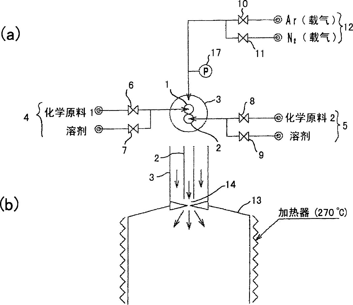
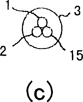
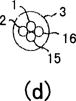
A vaporizer for CVD, a solution vaporizing CVD system and a vaporization method for CVD in which continuous use time is prolonged by suppressing clogging of solution piping, or the like. [MEANS FOR SOLVING PROBLEMS] The vaporizer for CVD comprises a plurality of material solution pipe lines (1, 2) for supplying a plurality of material solutions separatedly, a carrier gas pipe line (3) arranged to surround the outside of the plurality of material solution pipe lines (1, 2) and feeding compressed carrier gas respectively to the outsides of the plurality of material solution pipe lines (1, 2), a pore provided at the forward end of the carrier gas pipe line (3) while being spaced apart from the forward end of the material solution pipe lines (1, 2), a vaporization tube (13) connected with the forward end of the carrier gas pipe line (3) and linked to the interior of the carrier gas pipe line (3) through the pore, a mechanism for cleaning at least one of the forward end of the carrier gas pipe line (3), the pore and the vaporization tube (13), and a heater for heating the vaporization tube (13).

Description

technical field [0001] The present invention relates to a vaporizer for CVD, a solution vaporization type CVD apparatus, and a vaporization method for CVD, and particularly to a vaporizer for CVD, a vaporization method for CVD, and a vaporization method for CVD that use the above-mentioned CVD to prevent clogging of solution piping and the like and to be used continuously for a long time. A solution vaporization CVD apparatus using a vaporizer. Background technique [0002] From around 1970, the semiconductor industry introduced the technology of chemical vapor deposition CVD (chemical vapor deposition). When forming thin film materials, this technology flows the reaction material in the gas state into the reactor to cause a chemical reaction, and forms on semiconductor substrates such as silicon. Film materials of various compositions. However, if a gaseous reactive material cannot be prepared, thin films cannot be formed by CVD, which becomes a threshold for CVD technolog...

Claims


Application Information

Patent Timeline
Patent Type & Authority Applications(China)
IPC IPC(8): H01L21/205H01L21/31C23C16/448C30B25/14
CPCC23C16/4481C30B25/14
Inventor 矢元久良
Owner U TEC CO LTD
Why Eureka
Try Eureka