Pretensioner mechanism

A pre-tightening mechanism and component technology, which is applied to belt tighteners, energy-absorbing devices, seat belts in vehicles, etc., can solve the problem of increased restraint of seat belts on passengers, and achieve the effect of lengthening

Inactive Publication Date: 2012-02-01
KK TOKAI RIKA DENKI SEISAKUSHO
View PDF8 Cites 1 Cited by
  • Summary
  • Abstract
  • Description
  • Claims
  • Application Information

AI Technical Summary

Problems solved by technology

[0002] In the pretensioning mechanisms described in the following Patent Document 1 and Patent Document 2, gas is supplied into a tube (tubular cylinder), and

Method used


Image

  • Pretensioner mechanism
  • Pretensioner mechanism
  • Pretensioner mechanism

Examples


no. 1 Embodiment approach

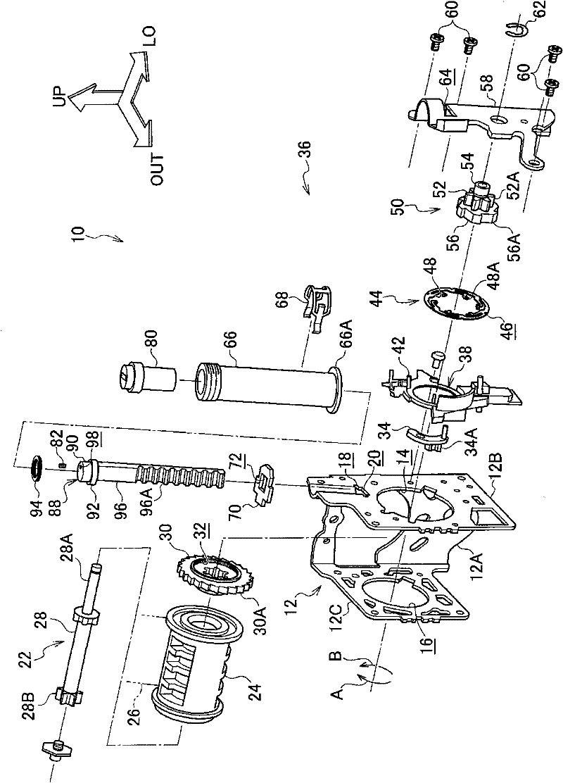
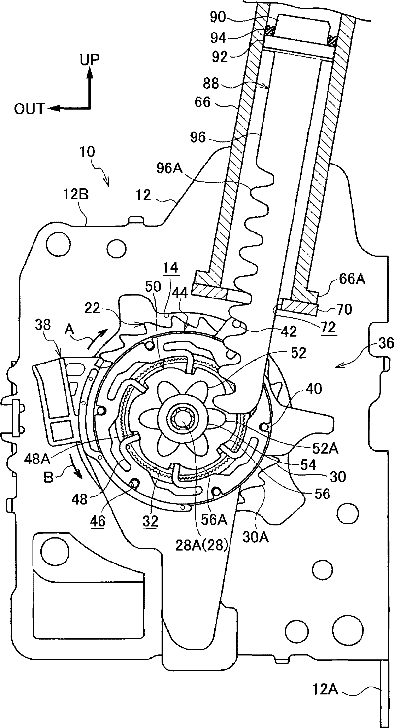
[0029] figure 2 The figure shows the seat belt take-up mechanism 10 to which the pretensioning mechanism 36 according to the first embodiment of the present invention is applied in an exploded perspective view viewed from the outside in the vehicle width direction and from one side in the vehicle front-rear direction, image 3 FIG. 3 shows the seat belt take-up device 10 in a side view viewed from one side in the front-rear direction of the vehicle. In addition, in the drawings, the outer side in the vehicle width direction is indicated by the arrow OUT, the one side in the front and rear direction of the vehicle is indicated by the arrow LO, and the upward direction is indicated by the arrow UP.

[0030] Such as figure 2 as well as image 3 As shown, in the seat belt take-up device 10 according to this embodiment, a plate-shaped frame 12 having a U-shaped cross section as a main body member is provided, and the frame 12 is provided with: The foot plate 12B on one side in...

no. 2 Embodiment approach

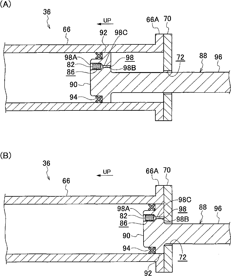
[0076] Figure 6 (A) and (B) are sectional views of main parts of the pretensioner mechanism 100 according to the second embodiment of the present invention.

[0077] The structure of the preload mechanism 100 according to this embodiment is basically the same as that of the above-mentioned first embodiment, but differs in the following points.

[0078] In the preload mechanism 100 according to this embodiment, the thread groove 86 is not formed on the peripheral surface of the closing member 82, but the thread groove 86 is formed on the peripheral surface of the large-diameter portion 98A of the communication hole 98, and the thread groove 86 has a spiral shape. shape, is arranged so as to be inclined with respect to the axial direction of the communicating hole 98 (the axial direction of the closing member 82 ), and communicates with the upper side and the lower side of the closing member 82 . The cross-sectional area of ​​the screw groove 86 is as small as possible within ...


PUM


Abstract

The present invention provides a pretensioner mechanism with easy operation in a state in which gas has been naturally released from inside a cylinder member when dismantling the cylinder member and a movement member after the movement member has been moved. In the pretensioner mechanism (36), a closure member (82) is pressed into a communication hole (98) of a piston (88) to close the communication hole. A thread groove (86) is formed on the peripheral face of the closure member (82) to communicate an upper side and a lower side of the closure member (82) to reduce the cross section of the thread groove (86). When the piston moves towards the lower side, the discharge of the gas in a cylinder (66) and closer to the upper side than the piston through the thread groove (86) towards the position closer to the lower side than the piston is reduced and the displacing force of the piston towards the lower side is supressed to be reduced. After the movement of the piston towards the lower side stops, the gas in the cylinder (66) and closer to the upper side than the piston is slowly cooled and discharged through the thread groove (86) towards the position closer to the lower side than the piston.

Description

technical field [0001] The present invention relates to a pretension mechanism, in which a movable member is moved by the pressure of gas supplied into a cylinder member, thereby increasing the restraining force of a seat belt on an occupant. Background technique [0002] In the pretensioning mechanisms described in the following Patent Document 1 and Patent Document 2, gas is supplied into a tube (tubular cylinder), and the pressure of the gas moves the piston (ball plug) to one side, so that the seat belt is tight against the seat belt. Personnel constraints increased. [0003] Here, in this kind of pretensioning mechanism, considering the recyclability, it is preferable that the tube and the piston can be disassembled. After the piston is moved to one side by the pressure of the gas, when the tube and the piston are disassembled, the gas in the tube will naturally It is easier to work if it is discharged from the ground. [0004] Patent Document 1: Japanese Patent Laid-...

Claims


Application Information

Patent Timeline
IPC IPC(8): B60R22/46
CPCB60R2022/4661B60R22/4633B60R22/46B60R22/48B60R22/28
Inventor 永田智纪朝雾佳规
Owner KK TOKAI RIKA DENKI SEISAKUSHO
Why Eureka
Try Eureka