
Subfield driving pixels in a display device

A display device and pixel technology, applied in the direction of static indicators, instruments, etc., can solve problems such as long time, and achieve the effect of increased life and reduced loss

Inactive Publication Date: 2006-01-11
KONINKLIJKE PHILIPS ELECTRONICS NV
View PDF1 Cites 2 Cited by
  • Summary
  • Abstract
  • Description
  • Claims
  • Application Information

AI Technical Summary

Problems solved by technology

This is ineffective because in many cases ON addressing takes longer than OFF addressing

Method used


Image

  • Subfield driving pixels in a display device
  • Subfield driving pixels in a display device
  • Subfield driving pixels in a display device

Examples


Embodiment Construction

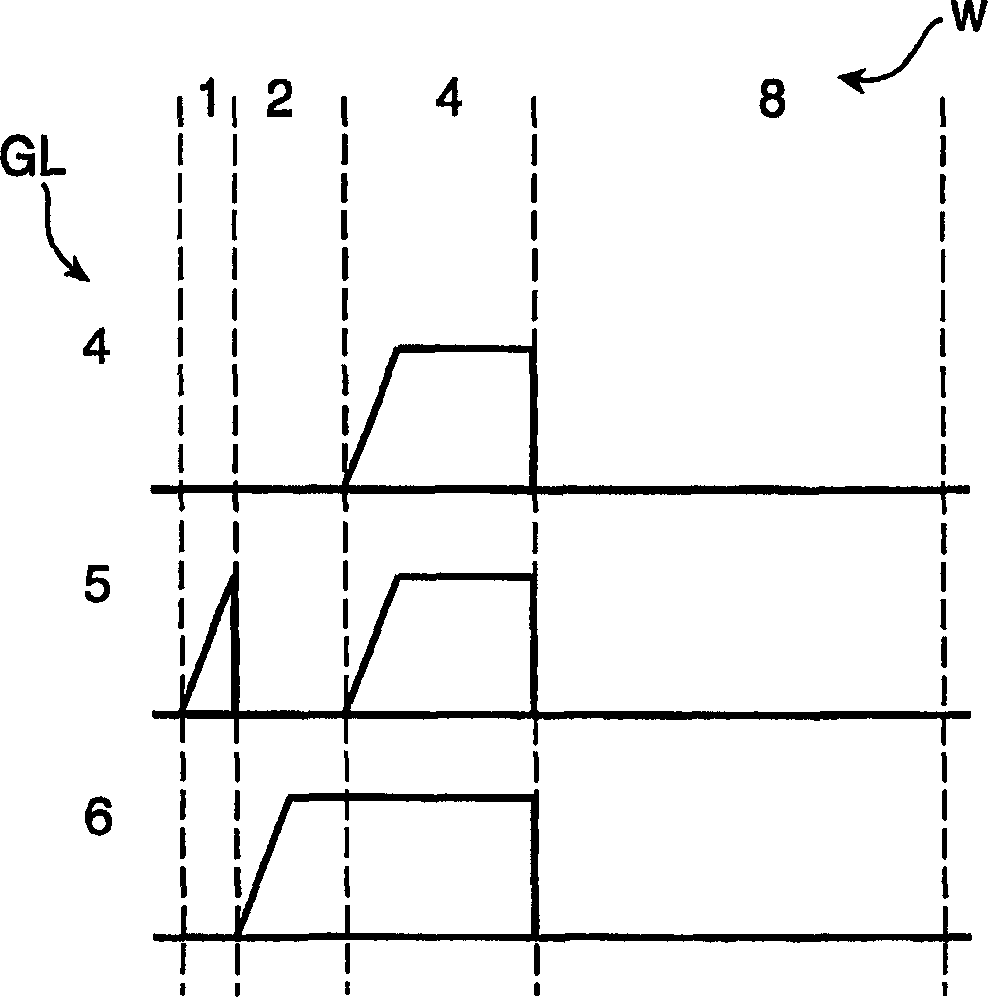
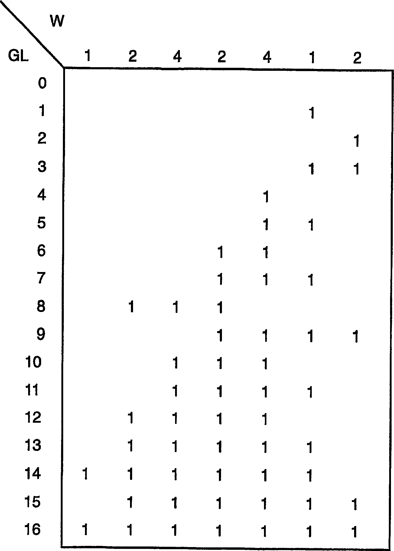
[0044] Figure 3-7 The first embodiment of the present invention is described in . to have image 3 Starting with the rightmost set of subfields corresponding to 4-1-2 weights W, the encoding scheme in these examples is designed. then in image 3 This sequence of subfields is continued (from right to left) with a weight W of 2-4-2-1 in the coding scheme of . This results in a coding scheme in which 17 different gray levels GL are generated on a linear scale from 0 to 16 using 7 subfields. Note that all gray levels GL consist of adjacent subfields, and the resulting addressing periods will have different start / end points. Figure 4 This situation is illustrated in , showing the generation of gray levels GL with values ​​4, 5 and 6. Thus, in the case of eg a PLED display, only one rise time tR is required per frame, independent of the gray level GL to be produced.

[0045] It should be noted that with the figure 1 In contrast to the pure Pulse Width Modulation (PWM) mecha...


PUM


Abstract

A method for driving pixels in a display device with an image signal is disclosed wherein the image signal comprises grey level information of an image to be rendered by the display device. The method comprises: dividing the image signal into sections, each section having a duration of a section period; dividing the section period into a plurality of adjacent, weighted sub-section periods; selecting for each of the pixels to be driven during the section period a sequence of adjacent sub-section periods in dependence on the grey level information, the selectable sequences lacking a common starting and ending point; driving the pixels during the sequences of adjacent sub-section periods. The method may be applied to displays driven by a pulse width modulated signal, such as sub-field as well as sub-line operated displays including plasma display panels, dynamic foil displays and passive displays.

Description

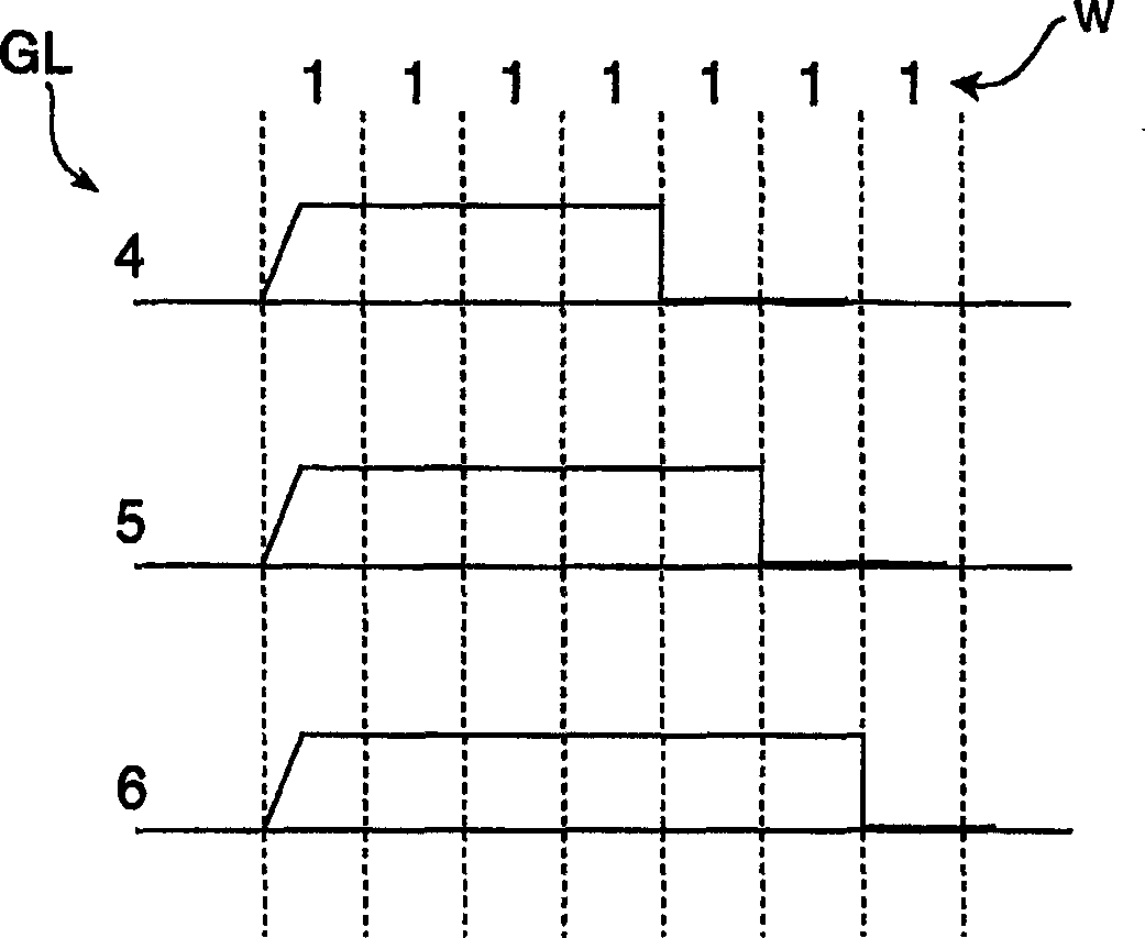
technical field [0001] The invention relates to a method of driving pixels in a display device. [0002] The invention also relates to a display device using the method. Background technique [0003] It is known that grayscale can be achieved in a display using pulse width modulation of an image signal, whereby a row scan period for driving pixels in a display frame of image data for a row is divided into N sub-row scan periods of equal duration. figure 1 It is described for grayscale GLs of sizes 4, 5, and 6 in . During driving, a pixel is turned on at the beginning of a row scan period and remains on for several consecutive sub-row scan periods required to achieve the desired gray level. Since the lengths of the sub-row scanning periods are equal, each sub-row scanning period contributes the same to the emitted light during the row scanning period, or in other words, each sub-row scanning period has an equal weight W. exist figure 1 The weight W of each subfield in is ...

Claims


Application Information

Patent Timeline
Patent Type & Authority Applications(China)
IPC IPC(8): G09G3/22G09G3/34G09G3/20G09G3/28G09G3/30
CPCG09G3/2029G09G3/2014G09G3/3433G09G3/2077G09G3/2022G09G3/20G09G3/30G09G3/32G09G3/296
Inventor D·A·科特J·范维泽恩R·范沃登伯格
Owner KONINKLIJKE PHILIPS ELECTRONICS NV
Learn More