
Spot lamp enlargement apparatus

A point light source and light source technology, applied in the field of optoelectronics, can solve the problems of increased cost, complicated operation, and bulky volume, and achieve the effect of convenient operation and simple structure

Inactive Publication Date: 2006-01-18
SOUTHWEST UNIVERSITY
View PDF0 Cites 0 Cited by
  • Summary
  • Abstract
  • Description
  • Claims
  • Application Information

AI Technical Summary

Problems solved by technology

[0003] 1. Substantial increase in cost
[0004] 2. Huge
[0005] 3. Complicated operation

Method used


Image

  • Spot lamp enlargement apparatus

Examples


Embodiment Construction

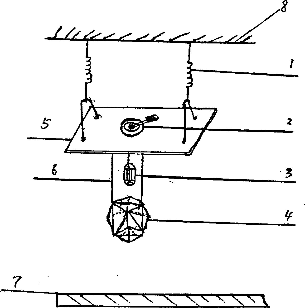
[0016] Combine below figure 1 The present invention is described further

[0017] Such as figure 1 As shown, the total reflection plate 5 is horizontally suspended under the hanger 8 by two springs 1, the small point light source 3 and the prism 4 are respectively suspended under the total reflection plate 5 by soft suspension wires, and the position of the prism 4 is lower than the small point The light source 3 and the lower light-receiving surface 7 are located below the prism 4 , and the twisting device 2 is fixedly installed on the total reflection plate 5 . The small point light source 3 and the twisting device 2 are controlled by an external electric control device and provided with power. After the small point light source 3 is energized, it emits light and shines on the side of the polygonal prism 4, and the light will change as follows: the light passes through the prism 4 and is transmitted to the lower part of the prism. The light is emitted from the bottom of th...


PUM


Abstract

The invention discloses a spot light aggrandizer which comprises a multi-part prism, wherein the upper part has small spot light; while the lower part has lower optical side; small spot and prism are hanged under reflect panel which is level hanged on the trapeze by spring and which has torsional device. The area of spot light can be extended on organism surface through the refraction and reflection of prism and the reflection of reflect panel, and then by the torsion of torsional device, the relative place of the spot light and prism and reflect plane changes, so that the light can produce many kinds of emitting forms.

Description

technical field [0001] The invention belongs to optoelectronic technology, and in particular relates to a point light source expansion device. Background technique [0002] Small point light sources such as lasers need to increase their illuminated area when they are used in many occasions. Since the illuminated area of ​​small point light sources is limited (for example, the area of ​​laser light is only 0.01 square centimeters), if you want to increase the illuminated area of ​​light, you can use The method is to increase the light source, that is, multiple small point light sources are required. For example, if the laser needs to increase the light irradiation area of ​​1 square centimeter, 100 laser light sources are needed; or the laser is enlarged with a convex lens, so that the light intensity per square centimeter is reduced. In order to increase the light intensity, only increase the power of the laser, which has the following disadvantages: [0003] 1. Substantial...

Claims


Application Information

Patent Timeline
Patent Type & Authority Applications(China)
IPC IPC(8): G02B27/09
Inventor 孙卫伟
Owner SOUTHWEST UNIVERSITY
Learn More