

Integrated circuit with automatic pin-strapping configuration
A technology for integrated circuits and configuration circuits, which is applied in the direction of logic circuits using specific components, logic circuits, logic circuits using basic logic circuit components, etc., and can solve problems such as impractical fine-tuning of chips
Inactive Publication Date: 2006-01-18
CIRRUS LOGIC INC
View PDF0 Cites 7 Cited by
- Summary
- Abstract
- Description
- Claims
- Application Information
AI Technical Summary
Problems solved by technology
However, in the past, it has been impractical to fine-tune the chip with external components
Method used
View moreImage
Smart ImageViewing Examples

Examples
Embodiment
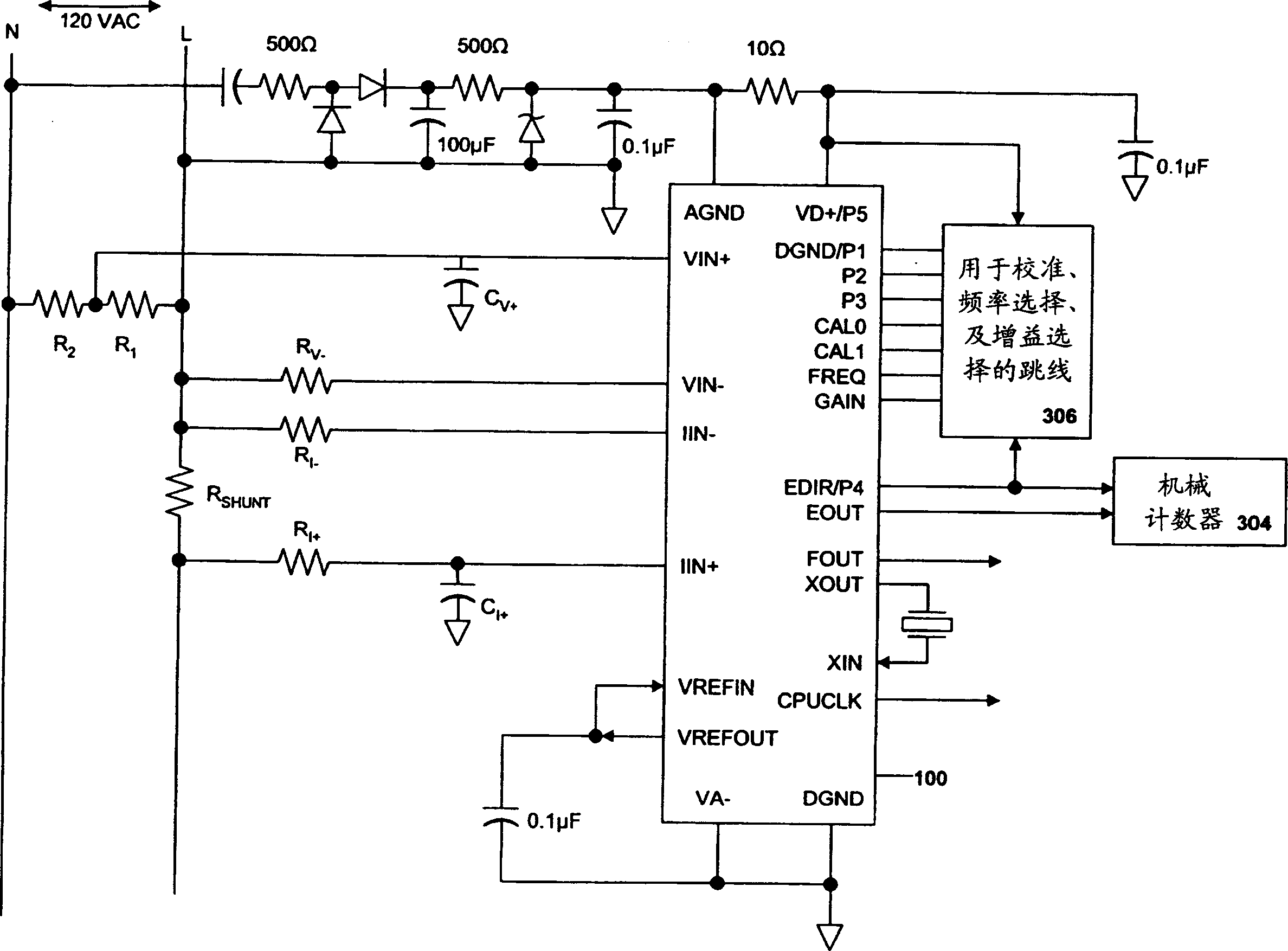
[0034] image 3An integrated circuit 100 of the present invention (an exemplary CS5462) is shown mounted to a system board 300 . The system board 300 is connected to a single phase, two wire branch line 302 and various system board components are connected to the chip 100 for measuring the power used. Power is tracked and read by a mechanical counter 304 . Configuration pins 224-228 are connected to program select pins P1-P5 214-222 via jumpers 306 on system board 300.
Login to View More PUM
 Abstract
An integrated circuit, in which one or more internal parameters may be automatically configured for a particular application, includes a plurality of program select pins, each being in a predetermined fixed state, and at least one configuration pin associated with a parameter to be adjusted. Jumpers on the system board to which the integrated circuit is mounted connect the mounting pad of each configuration pin with the mounting pad of a selected program select pin. Consequently, when the integrated circuit is mounted on the system board, each configuration pin receives a selected value which internal configuration circuitry detects and causes the corresponding parameter to be adjusted accordingly. Any of the program select pins may have functions in addition to the configuration function. When the system board is powered on or undergoes a reset, a processor internal to the chip scans each the configuration pin to determine its value. The processor then sets internal registers accordingly, completing the configuration process, and the chip may begin normal operation.
Description
technical field [0001] The present invention generally relates to the field of integrated circuits, and specifically relates to the configuration of internal parameters. Background technique [0002] Integrated circuits, or "chips," are usually mounted on a system board that is ultimately installed in the finished product. Typically, different manufacturers purchase integrated circuits for several (or more) different finished products. Therefore, a single-chip design must be tuned or configured for optimum performance in a particular product. Also, due to tolerances and other inaccuracies in other components, it is very important to be able to configure each chip when mounting the chips on a system board. [0003] It will be realized that it is impractical to use separate chip designs for similar applications. In the past, however, it has been impractical to fine-tune chips with external components. One prior art technique requires that designated chip pins be connected ...
Claims
Login to View More Application Information
Patent Timeline
 Patent Type & AuthorityApplications(China)
IPC IPC(8): G06F17/50H03K19/173
CPCH03K19/1732
Inventor弗兰克·登布雷耶恩戴维·迈克尔·比文威廉斯·詹姆斯·托克威廉·F·加尔代
OwnerCIRRUS LOGIC INC