D/A converter and driving method

A digital-to-analog and digital-signal conversion technology, applied in digital-to-analog converters, instruments, static indicators, etc., can solve the problems of large chip area and high manufacturing cost of source drivers

Inactive Publication Date: 2006-02-01
HANNSTAR DISPLAY CORPORATION
View PDF0 Cites 3 Cited by
  • Summary
  • Abstract
  • Description
  • Claims
  • Application Information

AI Technical Summary

Problems solved by technology

Moreover, by figure 1 It can be seen that every time a gray scale is increased, a switch and a reference voltage must be added to the digital-to-analog converter
As the display has higher and higher requirements for color resolution, the number of gray scales and switches required is also increasing, resulting in an increasing chip area, and the manufacturing cost of the source driver is also increasing. higher

Method used


Image

  • D/A converter and driving method
  • D/A converter and driving method
  • D/A converter and driving method

Examples


Embodiment Construction

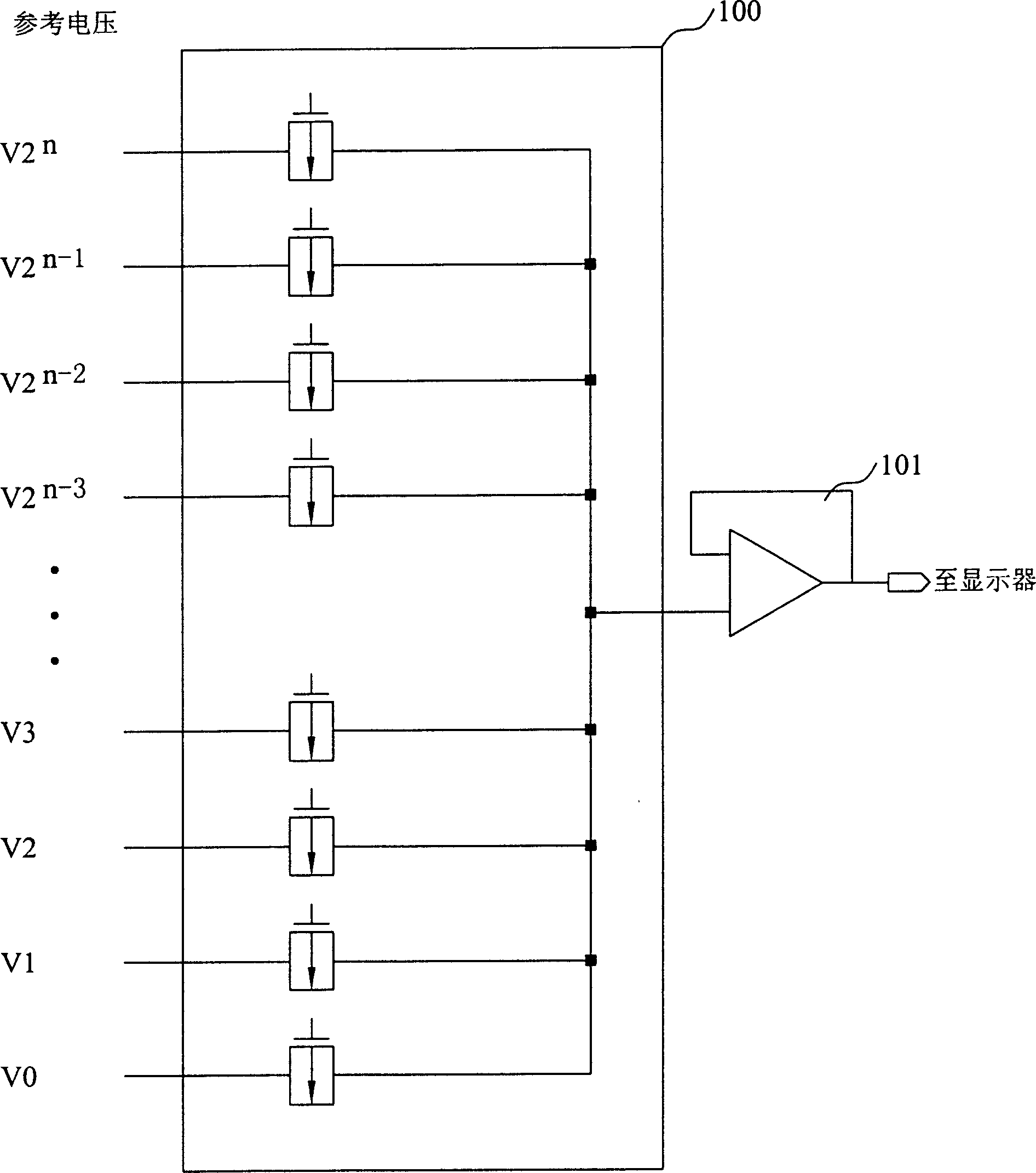
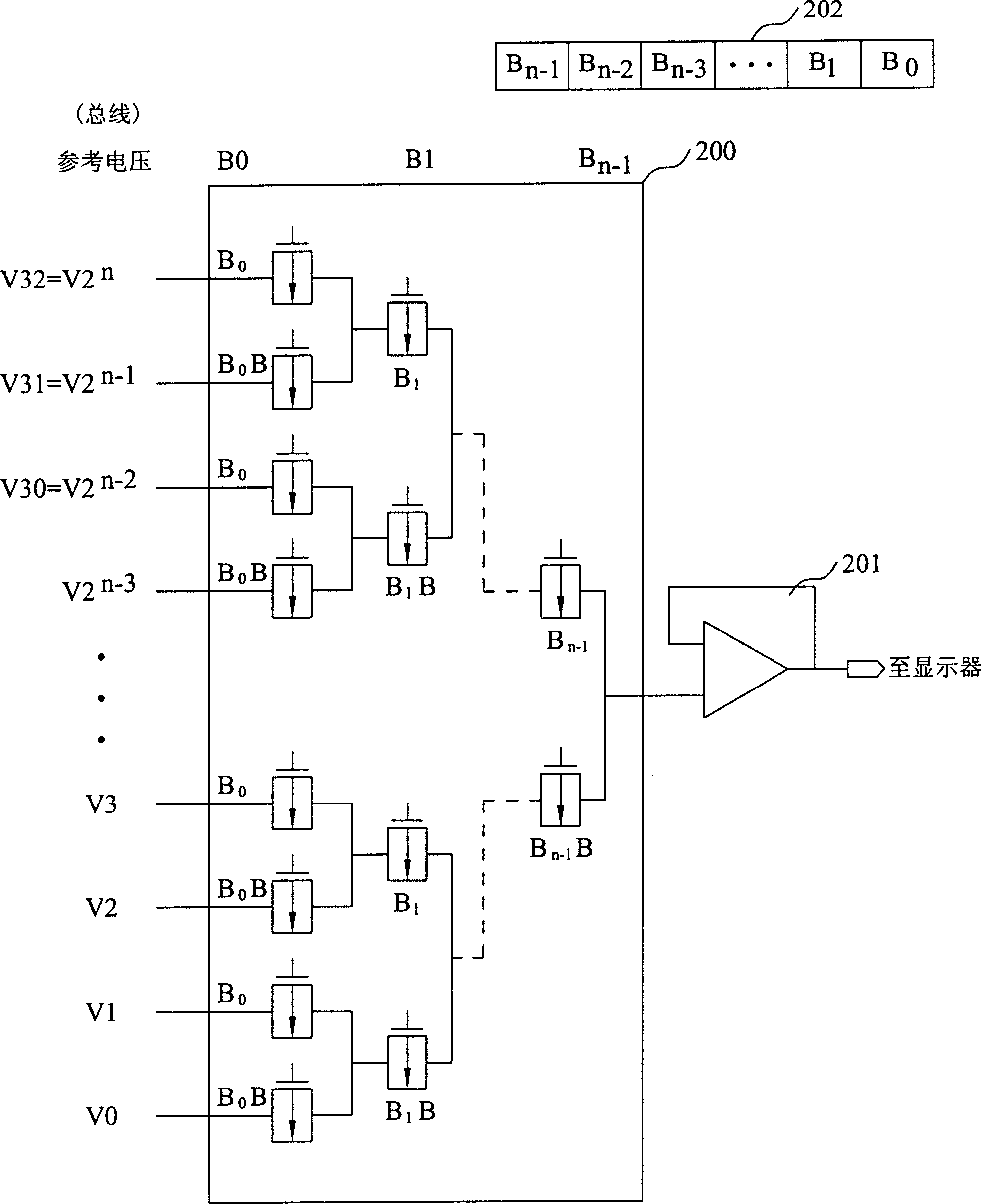
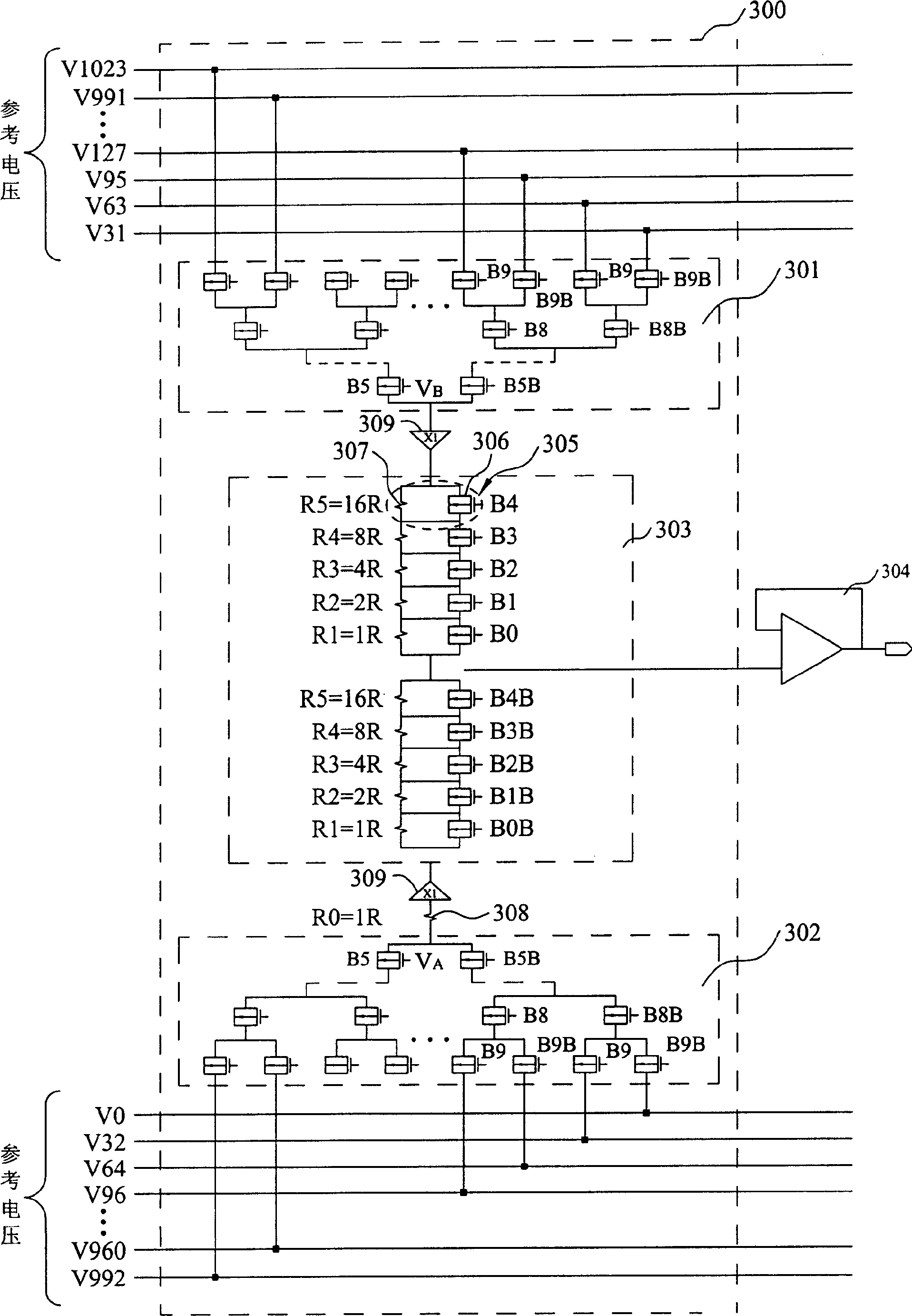
[0026] The present invention divides the digital-to-analog converter of the source driver into two parts, one is a high-level circuit that selects a reference voltage range from the reference voltage value, and the other is a low-level circuit that selects a voltage value from the reference voltage range circuit. In order to reduce the number of switches, the m+n bits of the input digital signal are divided into m high bits and n low bits. Among them, the m high bits select the highest and lowest reference voltage ranges of the digital-to-analog converter, and the other n low bits select a corresponding voltage value in the reference voltage range selected by the m high bits.

[0027] For ease of understanding, the following embodiments only take a 10-bit digital signal as an example to correspond to the 5 high-order bits (B 9 B 8 B 7 B 6 B 5 , representing 2 9 2 8 2 7 2 6 2 5 ) of the high circuit and the 5 low bits corresponding to this digital signal (B 4 B 3 B ...


PUM


Abstract

The method is in use for converting a digital signal to a value of voltage. The digital signal contains m+n digits. The method includes following steps: the digital signal is divided into first group and second group. The first group includes m pieces of first digit, and the second group includes n pieces of second digit. Based on m pieces of first digit in first group, a range of reference voltage is selected from multiple values of reference voltage. Finally, based on n pieces of second digit in second group, the value of voltage can be determined from the range of reference voltage.

Description

technical field [0001] The present invention relates to a circuit structure and driving method of a digital analog converter (Digital Analog Converter), in particular to a circuit structure and driving method of a digital analog converter inside a source driver in a display with high color resolution . Background technique [0002] Active Matrix Display (Active Matrix Display) refers to a component that uses transistors as pixel switches in a display. For example, in current displays, this active matrix display architecture is most widely used in thin-film transistor liquid crystal displays (TFT LCDs). . An active matrix display includes the following four parts: a display area of ​​the display, a gate driver (Gate Driver) circuit, a source driver (Source Driver) circuit, and a timing control circuit (Timing control Circuit). [0003] The display area of ​​the display uses the photoelectric properties of certain materials to convert electronic signals into light images. T...

Claims


Application Information

Patent Timeline
Patent Type & Authority Applications(China)
IPC IPC(8): H03M1/66G09G3/20G09G3/36
Inventor 王俊富白凤霆
Owner HANNSTAR DISPLAY CORPORATION
Why Eureka
Try Eureka