Flat knitting machine fabric stretching apparatus

A pulling device and fabric technology, applied in the directions of knitting, weft knitting, textile and paper making, etc., can solve the problem that the fabric cannot be automatically guided and pulled, etc., and achieve convenient operation of fabric winding, reduction of manufacturing cost, and smooth fabric. Effect

Inactive Publication Date: 2006-02-08
冯加林
View PDF0 Cites 17 Cited by
  • Summary
  • Abstract
  • Description
  • Claims
  • Application Information

AI Technical Summary

Problems solved by technology

The main disadvantage of this pulling device is that the fabric cannot be automatically guided and pulled, and the operator needs to manually operate in the initial stage to realize the guiding, pulling and winding of the fabric

Method used


Image

  • Flat knitting machine fabric stretching apparatus
  • Flat knitting machine fabric stretching apparatus
  • Flat knitting machine fabric stretching apparatus

Examples


Embodiment Construction

[0023] The present invention will be further described below in conjunction with the accompanying drawings and embodiments.

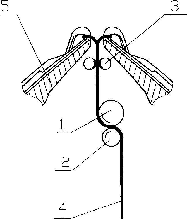
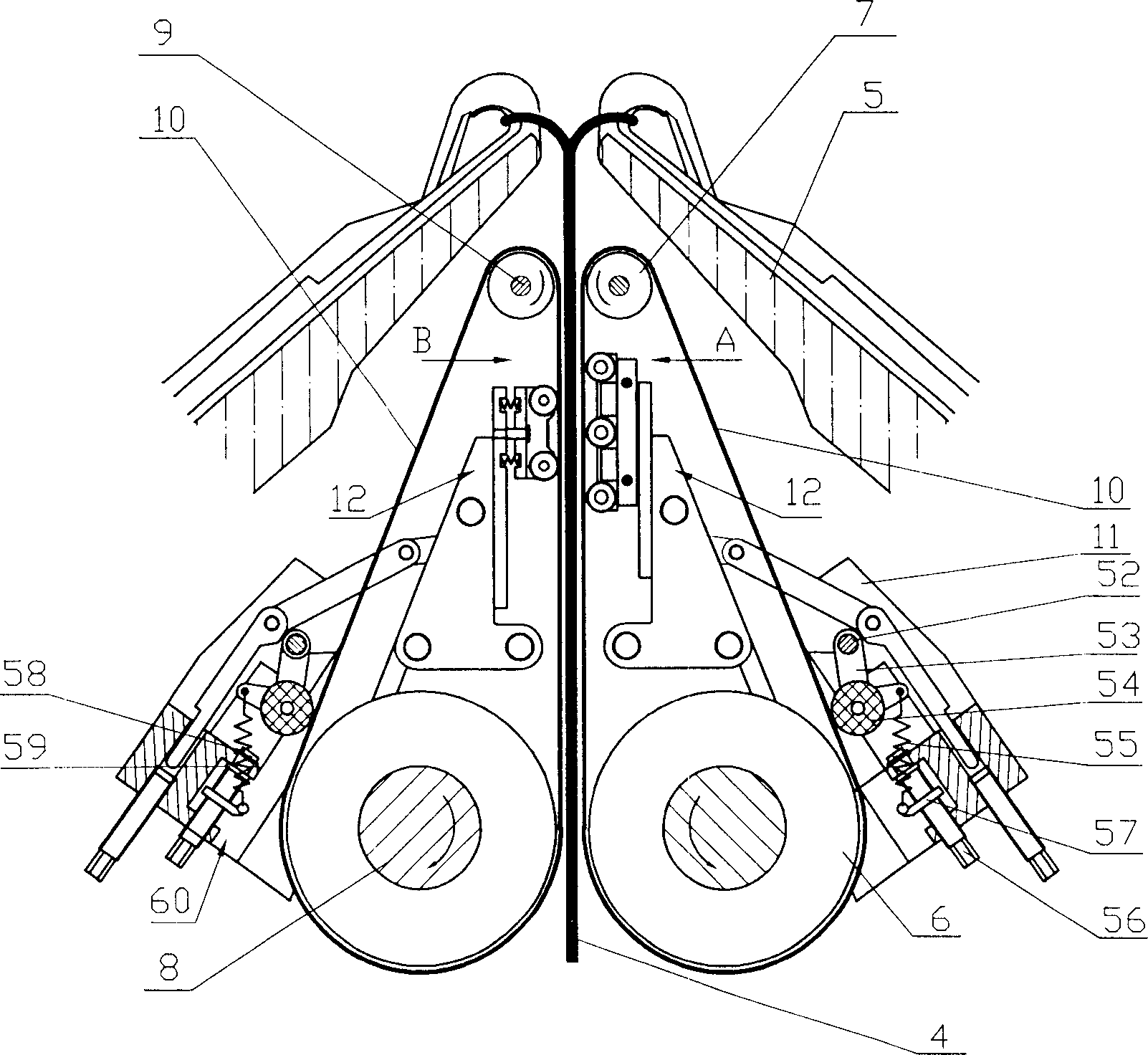
[0024] control figure 2 , the transmission mechanism on both sides of the conveyor belt composed of the large roller 6, the small roller 7, the large roller shaft 8, the small roller shaft 9, the conveyor belt 10 and the gap adjustment mechanism 12 is symmetrically placed on the lower side of the needle plate 5, the overall structure of the device of the present invention The triangular outline shape is very similar to the space on the lower side of the needle board, so the device of the present invention can be placed on the lower side of the needle board 5 very compactly, and the distance from the knitting needle to the device of the present invention is very small, only 20-30mm, and the fabric 4 The clamping length in the drive belt 10 can reach 200-250 mm, which is very beneficial to the flatness of the clamped and wound fabric 4 .

[0025] The la...


PUM


Abstract

The present invention relates to one kind of fabric drifting assembly of flat knitting machine. The technological scheme is that the fabric drifting assembly mounted on the frame and below the needle bed consists of two symmetrically set belt transmission mechanisms, and each of the belt transmission mechanisms includes large roller, small roller, large roller shaft, small roller shaft, transmission belt and interval regulating unit. The large roller and the small roller on the large roller shaft and the small roller shaft separately are connected via the transmission belt; the large roller shaft and the small roller shaft are set in parallel; the interval regulating unit is set in the inside transmission belt space between the large roller and the small roller; and the large roller shaft supported on the frame can shift in parallel. The present invention has the advantages of convenient fabric winding operation, high interval regulating efficiency, homogeneous drafting of the fabric, etc.

Description

technical field [0001] The invention relates to a flat knitting machine, and more specifically relates to a flat knitting fabric pulling device. Background technique [0002] At present, the pulling device in the flat knitting machine is as figure 1 As shown, it consists of two auxiliary rollers 3 that play a guiding role, a main pulling roller 1 that plays a pulling role, and a pressure roller 2 with a spring. The main pulling roller 1 is driven by a motor, and the pressure roller 2 is pressed against the main pulling roller 1 so that the pulled fabric basically has no slippage. The two auxiliary rollers 3 are driven by a special small motor, and the distance between the two axes can be adjusted. Adjustment, there are two adjustment positions of "tight" and "separate". When the fabric is woven to a certain length and falls from the gap between the needle plates on both sides, the operator needs to operate the handle of the auxiliary roller so that the two auxiliary roller...

Claims


Application Information

Patent Timeline
Patent Type & Authority Applications(China)
IPC IPC(8): D04B15/90
Inventor 冯加林巫友群
Owner 冯加林
Why Eureka
Try Eureka