Fixing device

A fixing device and mounting hole technology, applied in the directions of threaded fasteners, thin plate connections, connecting members, etc., can solve the problems of intrusion, poor operability, increase the insertion resistance of the pin 104, etc., to increase the pull-out force, Good operability

Inactive Publication Date: 2006-02-08
NIFCO INC
View PDF1 Cites 15 Cited by
  • Summary
  • Abstract
  • Description
  • Claims
  • Application Information

AI Technical Summary

Problems solved by technology

[0008] Therefore, although it is conceivable to reduce the inner diameter of the annular protrusion 110 in order to increase the pull-out force, this increases the insertion resistance of the pin 104 and deteriorates the operability.
[0009] On the one hand, in order to form the protruding portion in a direction perpendicular to the drawing direction of the mold, for example, although not shown in the figure, as in Patent Document 2 (Patent No. 3325121), a grommet bottom is provided with a When the through hole is formed, the through hole can be penetrated by the pin of the mold and the front end can be placed under the protruding part to form the protruding part. However, since the grommet is provided with a through hole, waste and water can be intrusion through via

Method used


Image

  • Fixing device
  • Fixing device
  • Fixing device

Examples


Embodiment Construction

[0035] Hereinafter, a fixing device according to an embodiment of the present invention will be described with reference to the accompanying drawings.

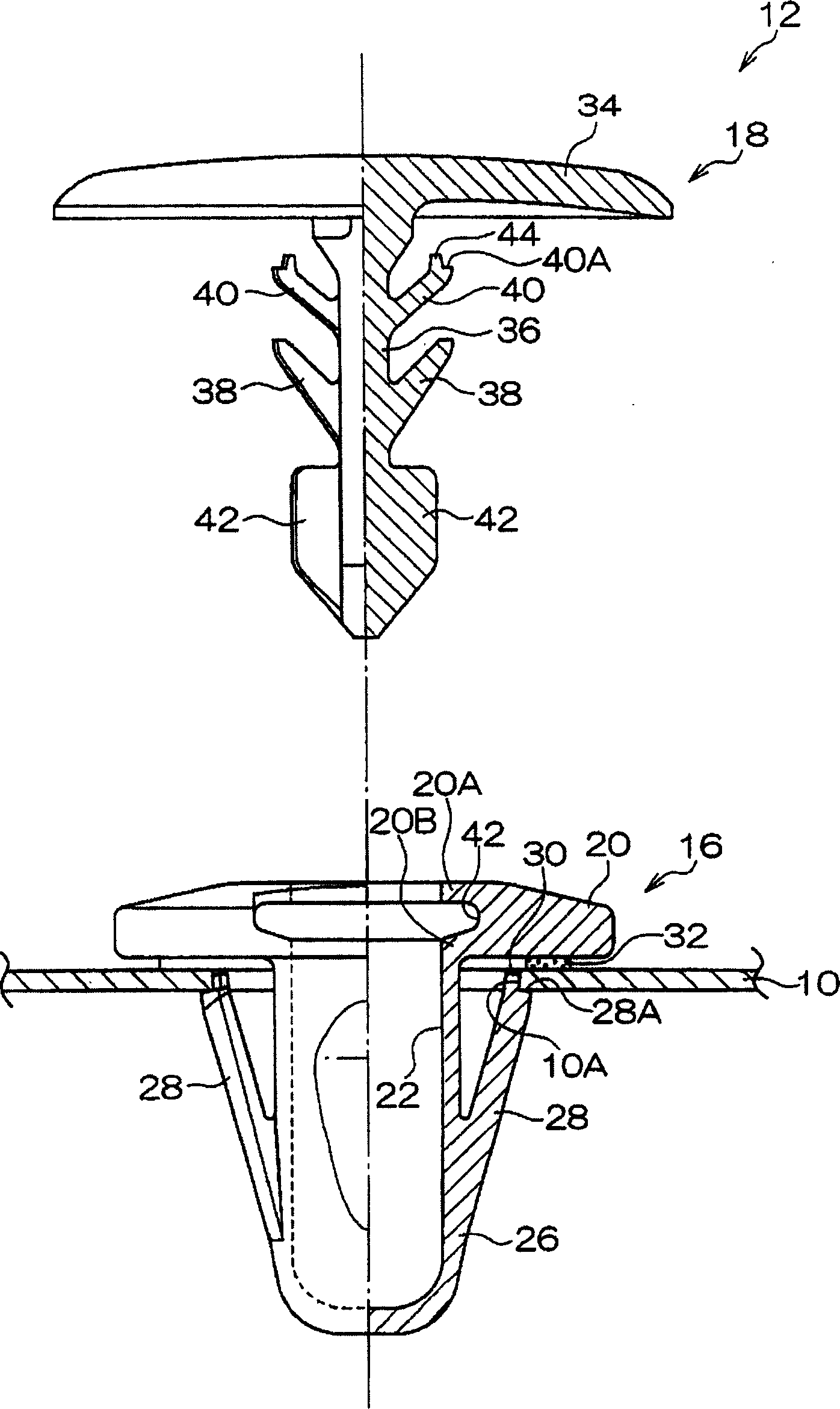
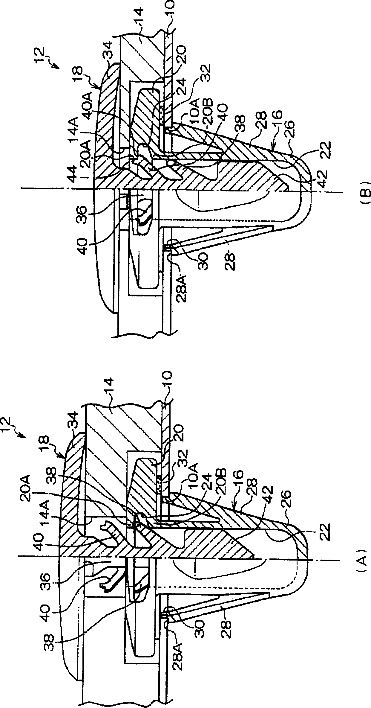
[0036] Such as figure 1 and image 3 As shown in (A), a carpet 14 is laid on the upper surface of the vehicle floor 10 with a fixing device 12 .

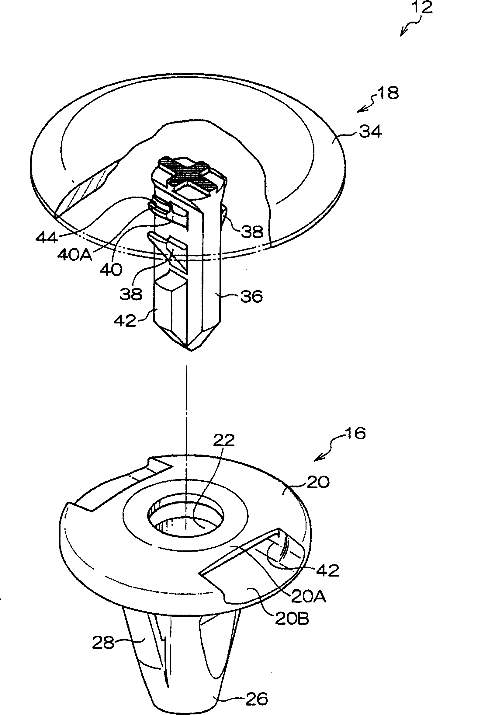
[0037] The fixing device 12 is composed of a cylindrical grommet 16 that can be inserted through the installation hole 10A formed on the vehicle floor 10 , and a pin 18 that is inserted through the installation hole 14A formed on the carpet 14 and is fastened in the grommet 16 .

[0038] The grommet 16 is provided with a thick-walled flange portion 20 , and the flange portion 20 is formed with a width dimension D in a direction perpendicular to the axial direction of the grommet 16 . 2 than the inner diameter dimension D of the insertion hole 22 1 Larger generally rectangular through hole 24 (see Figure 5 ). The through hole 24 divides the flange portion 20 into two parts, a...


PUM


Abstract

The present invention provides a fastener capable of preventing refuse and moisture from entering, raising an extraction force for a pin, and reducing insertion resistance in inserting the pin. Since a base 26 of a grommet 16 is formed in a bag shape, refuse and moisture do not enter into the base 26. Accordingly, water content does not ooze from the base 26 to a floor carpet 14 through an insertion hole 22 of the grommet 16. Also, a through hole 24 is formed in a flange 20 along a direction crossingly perpendicular to the axial direction of the grommet 16, and the flange 20 is divided into an upper part 20A and a lower part 20B. Accordingly, a locking claw 38 or a locking claw 40 can be locked to the upper part 20A. Since the upper part 20A of the flange 20 is recessed along a direction perpendicularly crossing the axial direction of the grommet 16, an extraction force can be increased more than in the case that the upper part 20A is formed in a tilted state relative to the axial direction of the grommet 16 despite the fact that the insertion resistance for the pin 18 is approximately the same.

Description

technical field [0001] The invention relates to a fixing device for fixing a carpet laid on a vehicle floor of a vehicle body to the vehicle floor. Background technique [0002] Conventionally, although the floor of the car interior is decorated by laying a carpet on the floor of the car, the carpet also functions as a soundproof material while protecting the floor of the car. [0003] In the process of laying the carpet on the vehicle floor in this way, the grommet which is clamped to the peripheral edge of the mounting hole formed in the vehicle floor and the grommet which holds the carpet together with the grommet and is clamped in the grommet are used. Fixtures made of pins. [0004] For example, if Figure 6 As shown, the fixing device of Patent Document 1 (JP-A-2000-249128) is to fasten the pin 104 to the grommet after installing the grommet 100 to the plate 102 and the pin 104 to the cover top 106. 100, and fix the dome 106 to the object on the plate 102. [0005] ...

Claims


Application Information

Patent Timeline
Patent Type & Authority Applications(China)
IPC IPC(8): F16B19/00F16B5/00
Inventor 矶村恒久
Owner NIFCO INC
Why Eureka
Try Eureka