Hall linear displacement transducer without lead

A linear displacement, sensor technology, applied in the direction of using electric/magnetic devices to transmit sensing components, can solve the problems of measurement range influence, short service life, influence measurement accuracy, etc., to improve measurement accuracy, improve service life, increase The effect of a large measuring range

Inactive Publication Date: 2006-02-08
孙钢
View PDF0 Cites 4 Cited by
  • Summary
  • Abstract
  • Description
  • Claims
  • Application Information

AI Technical Summary

Problems solved by technology

The biggest disadvantages of the sensor with this structure in actual use are: (1) The Hall element is directly used as a moving part. Since the Hall element has four working wires, when the Hall element moves, the four working wires will follow the Hall element. Moving together, it is easy to make the lead wire fatigue and break, especially when the object is reciprocating at high speed and frequently, and the service life is short; (2) In order to ensure a certain service life, the lead wire of the Hall element must have a certain strength And flexible, when the lead is bent and deformed, it will produce a certain elastic force, which will generate an additional force on the moving parts, which will cause the position of the moving parts to change and cause measurement errors
This is especially evident in the measurement of micro-moving bodies; (3) When the Hall element moves in a straight line, the angle between the sensitive surface of the Hall element and the magnetic field B will be offset and shaken due to the influence of mechanical dynamic coordination factors. At the same time, the distance between the magnet and the Hall element will also change, resulting in a change in the output of the Hall potential, seriously affecting the measurement accuracy; (4) limited by the magnetic circuit system, its measurement range is affected to a certain extent, and the range is small

Method used


Image

  • Hall linear displacement transducer without lead

Examples


Embodiment Construction

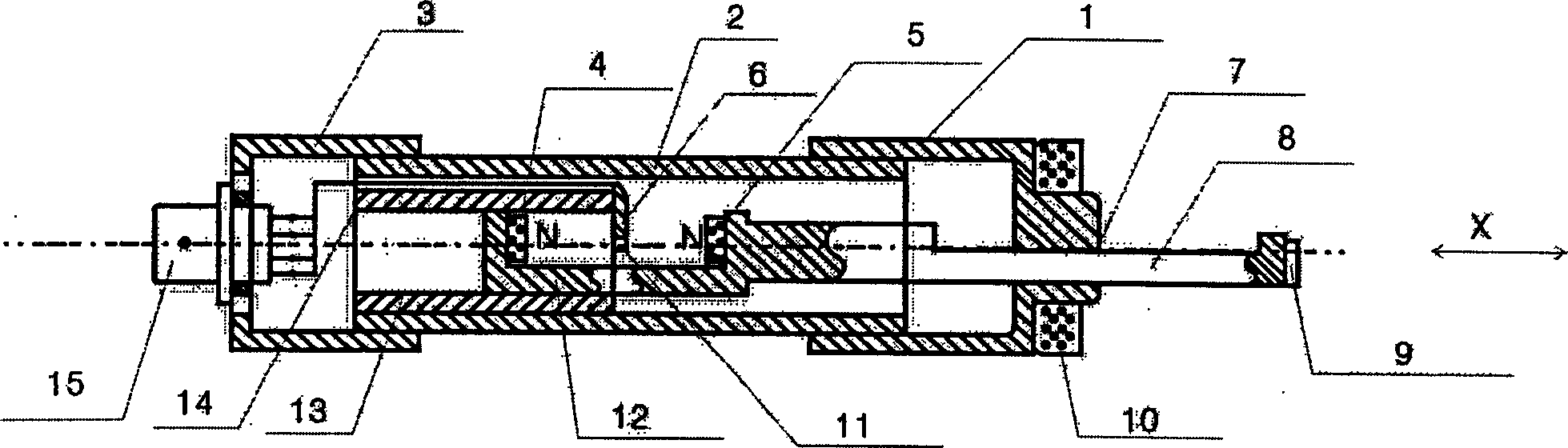
[0011] As shown in the accompanying drawings, the uninvolved Hall linear displacement sensor has a connected front end cover 1, an outer cover 2, and a rear end cover 3. An inner sleeve 13 is provided in the outer cover near the rear end cover, and the front end cover 1 is equipped with a measuring rod 8. , the surface of the measuring rod 8 is provided with an anti-rotation surface 7, the outer end of the measuring rod is provided with a permanent magnet 9, the inner end of the measuring rod is connected with a magnetic steel seat 12, and the magnetic steel seat 12 is provided with a first permanent magnet 4 and a second permanent magnet. The magnetic steel 5 and the first permanent magnetic steel 4 are in the inner sleeve, the end surface of the inner sleeve is provided with a printed board 6 and a Hall element 11, and the outer end of the rear end cover 3 is provided with a socket 15.

[0012] The length of interior cover 13 is the half of overcoat 2 lengths. The anti-rotat...


PUM


Abstract

The invention discloses a non-involvement Hall linear displacement sensor. It possesses a connected front end cap, a fur and a rear end cap, wherein the inner fur is positioned inside the fur and besides to the rear end cap; the measuring rod is through with the front end cap; the anti-rotating side is positioned on the surface of the measuring rod; the permanent-magnet steel is positioned on the outside of the measuring rod; the magnet steel seat with first permanent-magnet steel in the inner fur and second permanent-magnet steel is connected with the inner side of the measuring rod; the printing plate and the Hall unit are positioned on the end cap of the inner fur; the pad is positioned on the outside of the rear end cap. The moving part is the measuring rod, which drives two permanent-magnet steels without lead-line; it adopts flat cylinder magnet steel and fixes the Hall unit on the middle axle of the two magnet steels, so that the outputted Hall electric potential is stable.

Description

technical field [0001] The invention relates to an uninvolved Hall linear displacement sensor. Background technique [0002] At present, the existing Hall linear displacement sensor structures on the market are composed of Hall elements moving linearly in a magnetic field, and various related teaching materials in colleges and universities also use this structure as an explanation. The biggest disadvantages of the sensor with this structure in actual use are: (1) The Hall element is directly used as a moving part. Since the Hall element has four working wires, when the Hall element moves, the four working wires will follow the Hall element. Moving together, it is easy to make the lead wire fatigue and break, especially when the object is reciprocating at high speed and frequently, and the service life is short; (2) In order to ensure a certain service life, the lead wire of the Hall element must have a certain strength And flexible, when the lead wire is bent and deformed, ...

Claims


Application Information

Patent Timeline
Patent Type & Authority Applications(China)
IPC IPC(8): G01D5/12
Inventor 孙钢
Owner 孙钢
Why Eureka
Try Eureka