Inter-axle differential assembly

一种动组件、轴组件的技术,应用在交互轴差动组件领域,能够解决元件耐用性不利影响等问题

Inactive Publication Date: 2006-02-15
ARVINMERITOR TECH
View PDF0 Cites 7 Cited by
  • Summary
  • Abstract
  • Description
  • Claims
  • Application Information

AI Technical Summary

Problems solved by technology

Larger powertrain corners can adversely affect component durability

Method used


Image

  • Inter-axle differential assembly
  • Inter-axle differential assembly
  • Inter-axle differential assembly

Examples


Embodiment Construction

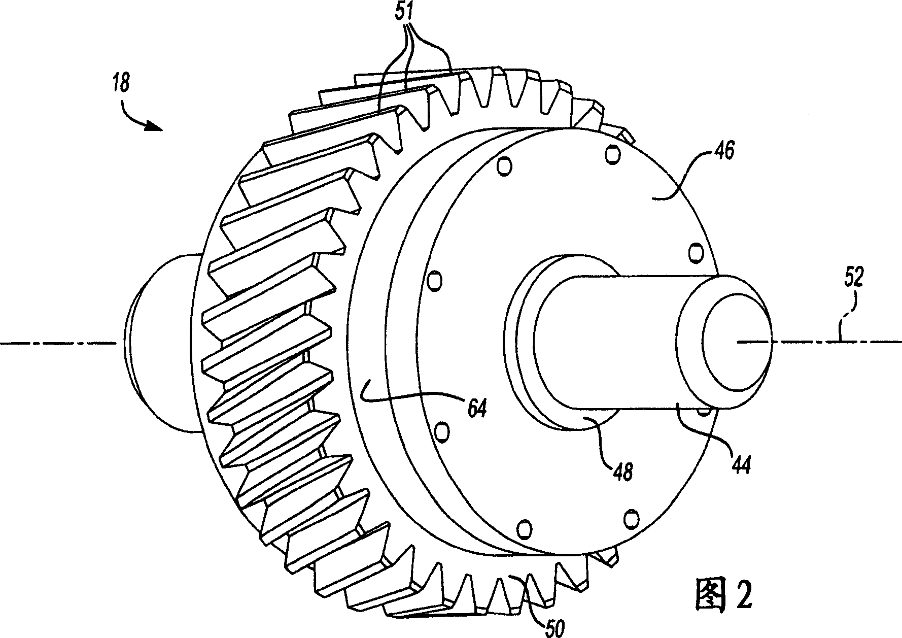
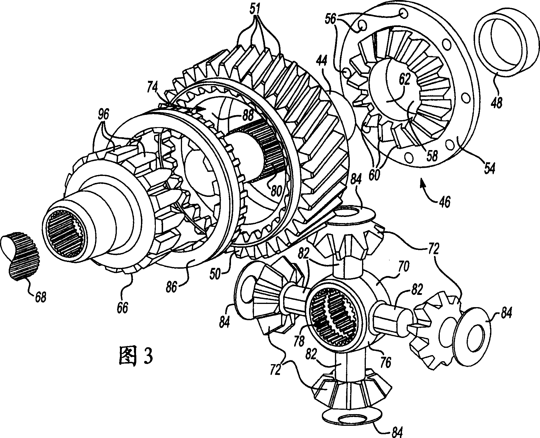
[0022] Shown in FIG. 1 is a tandem drive shaft 10 . The tandem driveshaft 10 includes a front axle 12 and a rear axle 14 coupled to the front axle 12 with a connecting driveshaft 16 . The front axle 12 includes an intershaft differential gear assembly 18 coupled to a drive shaft 20 driven by a power source 22, such as an engine or electric motor. Other powertrain components, such as transmissions, gearboxes, clutches, or any other known powertrain components, may be interposed between the power source 22 and the drive shaft 20 as is known in the art. The cross axle differential gear assembly 18 provides a speed differential between the front axle 12 and rear axle 14 as is known.

[0023] The front axle 12 includes a front differential gear assembly 24 coupled to a front drive shaft 26 for driving a pair of transversely opposed front wheel ends 28 . The rear axle 14 includes a rear differential gear assembly 30 coupled to a rear drive shaft 32 for driving a pair of transverse...


PUM


Abstract

An inter-axle differential assembly includes a forward side gear and a rear side gear that are supported by an input shaft. The forward and rear side gears are in meshing engagement with a plurality of inter-axle differential pinion gears that are supported on a spider. The spider is driven by the input shaft and has a plurality of legs with each leg supporting one of the plurality of inter-axle differential pinion gears. A helical drive gear is fixed for rotation with the forward side gear. The helical drive gear includes a center cavity defined by a spherical inner surface. The spider and the plurality of inter-axle differential pinion gears are positioned within the center cavity. This eliminates the need for an inter-axle differential housing assembly and reduces standout.

Description

technical field [0001] The present invention relates to an alternating shaft differential assembly comprising a front gear for rotation with a helical drive gear and alternating shaft differential gear. Background technique [0002] Typically, a tandem drive shaft is used to drive the rear wheels of a heavy commercial vehicle, such as a trailer. The tandem driveshafts include a front driveshaft and a rear driveshaft connected by an interconnecting driveshaft. The tandem drive shaft includes an intershaft differential assembly that may allow a speed differential between the front drive shaft and the rear drive shaft. The differential assembly is used to provide a desired speed differential between the drive input to the front differential gear assembly used in the front drive shaft and the drive input to the rear differential gear assembly used in the rear drive shaft . [0003] A typical cross shaft differential assembly includes a rear side gear, cross shaft differentia...

Claims


Application Information

Patent Timeline
Patent Type & Authority Applications(China)
IPC IPC(8): F16H48/06F16H48/20
CPCB60K17/36F16H48/08
Inventor A·J·R·阿尔马古尔
Owner ARVINMERITOR TECH
Why Eureka
Try Eureka