

Signal transmission method and device
一种信号传送装置、信号传送的技术,应用在光通信领域,能够解决接入节点容器利用率降低、网络带宽利用率低等问题
- Summary
- Abstract
- Description
- Claims
- Application Information
AI Technical Summary
Problems solved by technology
Method used
Image

Examples
Embodiment Construction
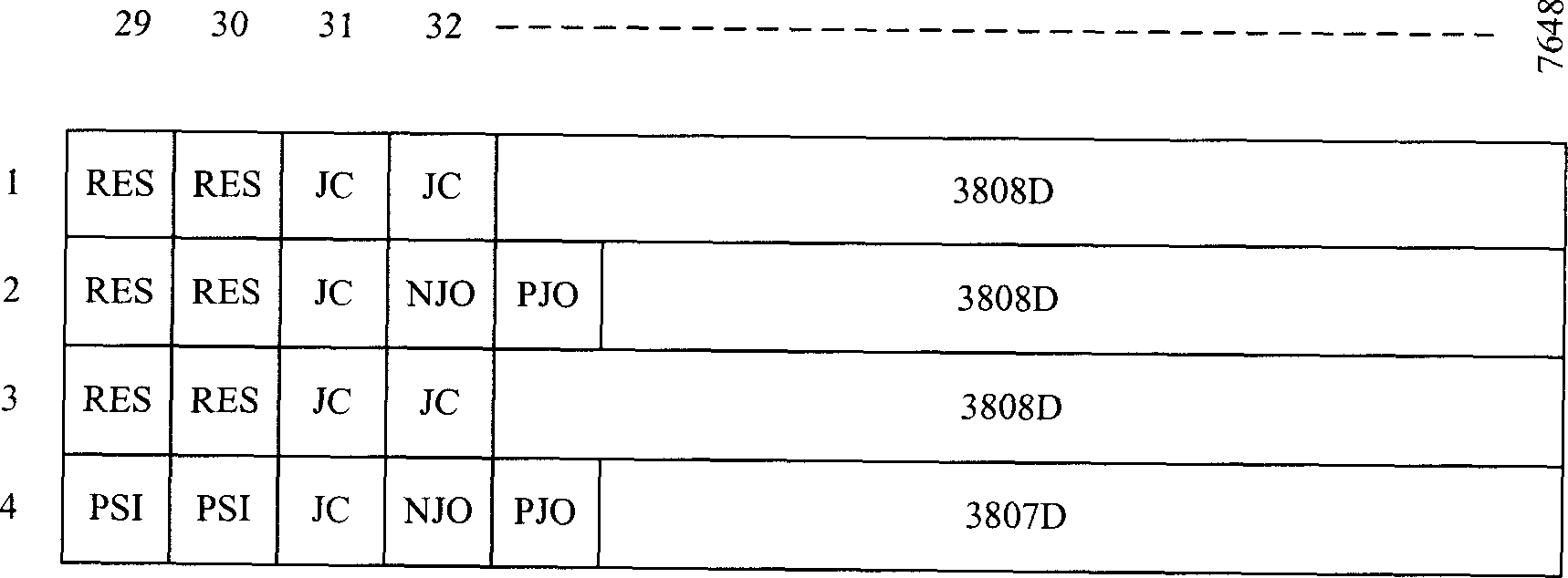
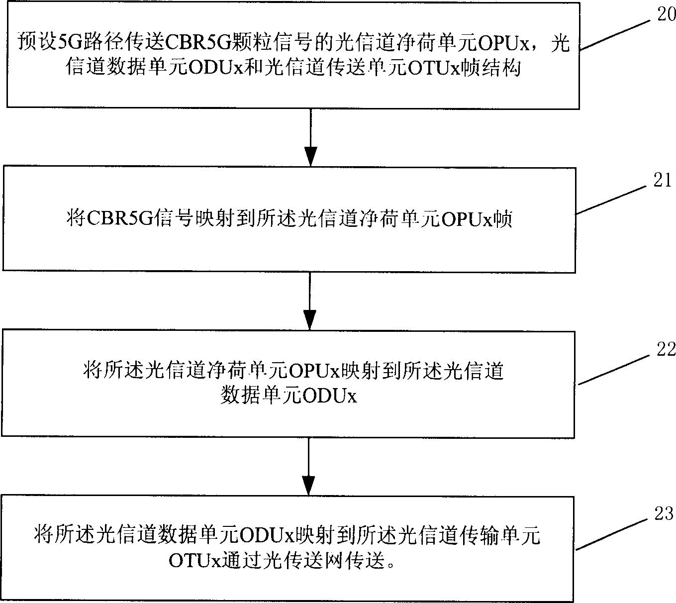
[0123] The signal transmission method and device of the present invention are used to map the CBR5Gbps (hereinafter referred to as CBR5G) signal to the OTN network for transparent transmission, so as to realize the direct scheduling, monitoring and management of the CBR5G granular signal in the OTN, and improve the OTM multiplexing and mapping structure , to improve the flexibility of customer signal multiplexing and mapping.
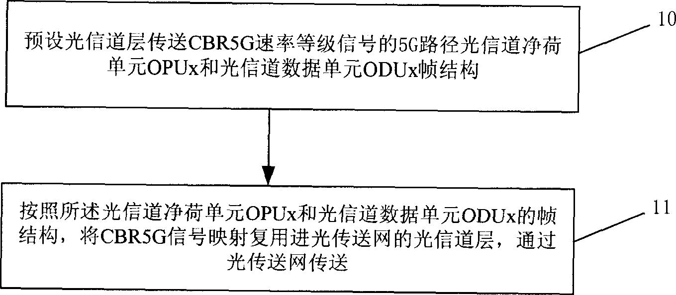
[0124] refer to figure 2 , which is the main flowchart of the signal transmission method of the present invention.
[0125] First, in step 10, the optical channel (Och) layer is preset to transmit the 5G path optical channel payload unit OPUx and optical channel data unit ODUx frame structure of the CBR5G rate level signal. During specific implementation, the data frame defined by the relevant standard protocol can be used Structure design, such as G.709 protocol, etc.
[0126] Then, in step 11, according to the frame structure of the optical channel...
PUM
 Abstract
Description
Claims
Application Information