
Apparatus for reading from and/or writing to optical recording media

An optical recording medium and recording medium technology, applied in the direction of optical recording/reproduction, optical recording head, data recording, etc., can solve the problem of increasing the absolute value of loss

Inactive Publication Date: 2006-02-15
THOMSON LICENSING SA
View PDF2 Cites 0 Cited by
  • Summary
  • Abstract
  • Description
  • Claims
  • Application Information

AI Technical Summary

Problems solved by technology

In addition, the LC element has the disadvantage that the absolute value of its transmission loss is 10-20%
If the outgoing input beam and the returning data beam are affected by the LC element, the absolute value of the loss increases to 40%

Method used


Image

  • Apparatus for reading from and/or writing to optical recording media
  • Apparatus for reading from and/or writing to optical recording media
  • Apparatus for reading from and/or writing to optical recording media

Examples


Embodiment Construction

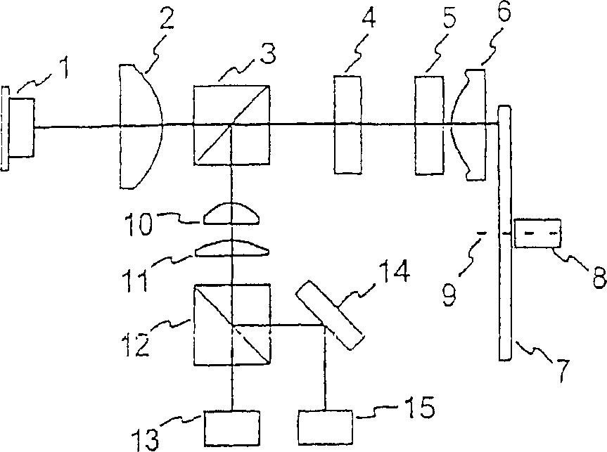
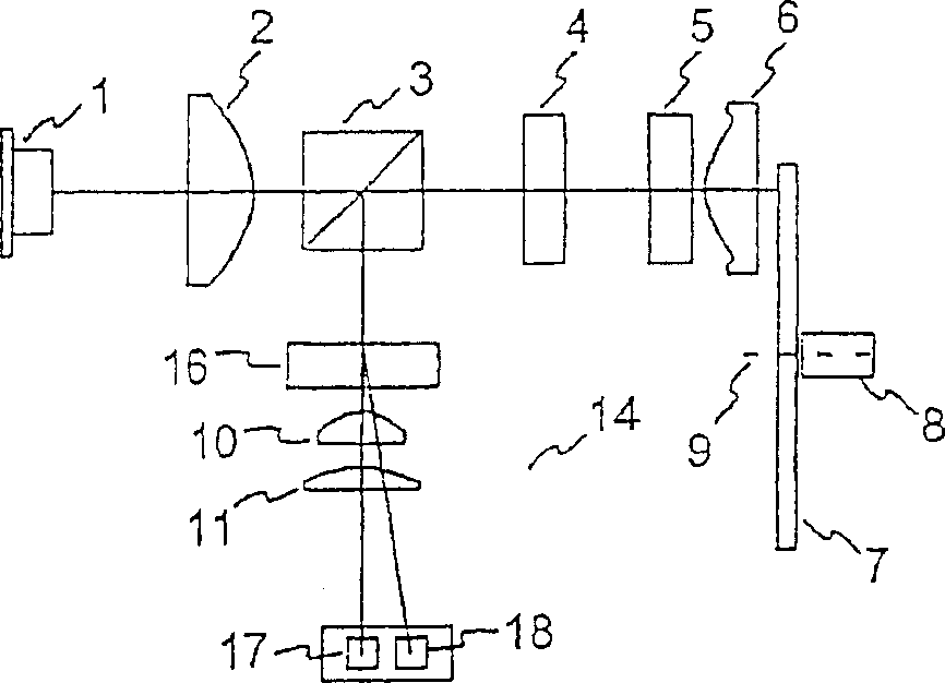
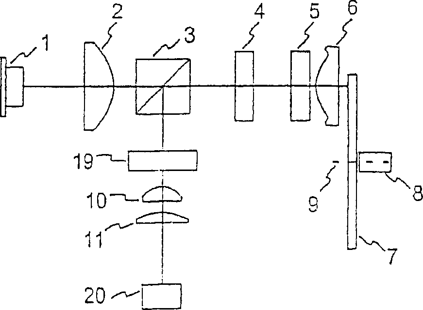
[0020] All systems have an emission source 1, preferably a laser diode, which emits a linearly polarized beam. The emitted light is collimated into parallel light by the collimating lens 2, and passes through the polarizing beam splitter 3, and the polarizing beam splitter 3 passes through the light polarized in the first direction without hindrance, and will Light polarized in the direction of the first direction is deflected by 90°. The polarizing beam splitter 3 is adjusted so that the beam from the emission source 1 is not deflected. The next step is that the beam passes through the LC element 4, which can be driven electrically and, due to its design, is able to manipulate the wavefront of the incident beam. Such devices are known and described eg in US 6,182,957 or in US 5,909,422. In the present invention, the LC element 4 is designed to respond to light beams in only one polarization direction, which substantially simplifies the design and driving process.

[0021] ...


PUM


Abstract

When an optical recording medium (7) having a plurality of data layers is being read from and / or written to, the input beam experiences an aberration, inter alia in the top layers of the data layers. In order, nevertheless, to achieve a high data density, a device (4) for correcting the spherical aberration is located in the beam path of the input beam. In the case of the use of an optical diode in which the input beam and the reflected beam have directions of polarization perpendicular to one another, such a device (4) is expensive to implement and associated with a reduced optical efficiency. It is an object of the invention to propose an apparatus for reading from and / or writing to optical recording media, in the case of which a high optical efficiency and balancing of the spherical aberration are achieved with low outlay. For this purpose, the device (4) for correcting the spherical aberration is set up such that the reflected beam traverses it uninfluenced, whereby means (12, 16, 19) for correcting the imaging of the reflected beam onto at least one detector unit (13, 15, 17, 18, 20) are provided in the further beam path.

Description

technical field [0001] The invention relates to a device for reading from and / or writing to an optical recording medium, the device having means for correcting optical aberrations. Background technique [0002] Such devices use a read or write beam (indicated below as input beam) emitted by an emitting source, usually a laser diode, to read from or write to the data layer of the optical recording medium. The light beam emitted by the emission source is first parallelized by a collimator lens and then passed through a beam splitter before being focused onto the data layer by an objective lens that is movable perpendicular to the data layer of the recording medium. The data beams projected oppositely to the input beams are produced by local reflections of the input beams at the data layer structures representing the data and arranged in the form of tracks. The data beam is transformed into parallel light by the objective lens, deflected to the direction of the detector unit b...

Claims


Application Information

Patent Timeline
Patent Type & Authority Applications(China)
IPC IPC(8): G11B7/135G11B7/00
CPCG11B7/13925G11B7/1381G11B2007/0013G11B7/1369G11B7/1353G11B7/1395
Inventor 乔基姆·尼特尔哈特穆特·里克特
Owner THOMSON LICENSING SA
Learn More