Emission detection method

A detection method and technology for emitting light, applied in the field of emitted light detection, can solve problems such as low experimental efficiency

Active Publication Date: 2021-07-06
INTEGRATED BIOSYSTEMS CO LTD +1
View PDF10 Cites 0 Cited by
  • Summary
  • Abstract
  • Description
  • Claims
  • Application Information

AI Technical Summary

Problems solved by technology

[0004] For this reason, the present invention provides a kind of emission light detection method, in order to solve the problem of low experimental efficiency in the prior art

Method used

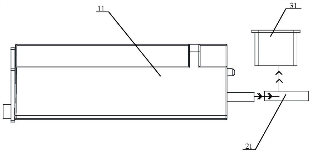
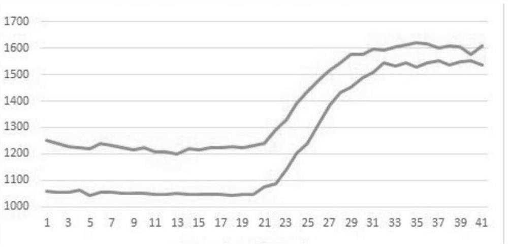
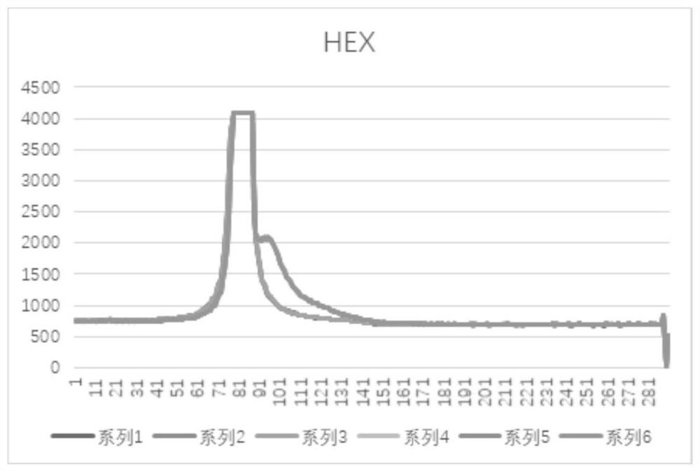

Image

  • Emission detection method
  • Emission detection method
  • Emission detection method

Examples


Embodiment Construction

[0035] In order to make the objects and advantages of the present invention clearer, the present invention will be further described below in conjunction with the examples; it should be understood that the specific examples described here are only for explaining the present invention, and are not intended to limit the present invention.

[0036] Preferred embodiments of the present invention are described below with reference to the accompanying drawings. Those skilled in the art should understand that these embodiments are only used to explain the technical principle of the present invention, and are not intended to limit the protection scope of the present invention.

[0037] It should be noted that, in the description of the present invention, terms such as "upper", "lower", "left", "right", "inner", "outer" and other indicated directions or positional relationships are based on the terms shown in the accompanying drawings. The direction or positional relationship shown is ...


PUM


Abstract

The invention relates to an emission light detection method. The emission light detection method comprises: a plurality of excitation light sources irradiating the substance to be detected according to a preset method, so as to excite the substance to be detected, so that the emission light detection device detects the emission light generated by the substance to be detected. ; The substance to be detected contains a fluorescent group, which is used to generate emission light under the excitation of the excitation light; the emission light detection device is arranged on the optical path of the emission light, and captures and detects the emission light; in the same detection process, each excitation light source according to The preset M test cycles emit excitation light, and each excitation light sequentially completes the excitation of M test cycles, and the emission light detection device obtains the corresponding light emitted by each excitation light within the preset M test cycles. emit light. The emitted light detection method provided by the embodiment of the present invention has multiple excitation light sources, which can be detected simultaneously, and the emitted light detection device continuously acquires the intensity of emitted light, so that the experiment efficiency is high, convenient and efficient.

Description

technical field [0001] The invention relates to the field of biological detection, in particular to an emission light detection method. Background technique [0002] In recent years, fluorescence analysis technology has been widely used in scientific research and production. Fluorescence analysis technology refers to that the excitation light device of a certain wavelength is irradiated on the substance to be detected, and the atoms or molecules in the substance to be detected absorb the energy of the excitation light, and the produce transitions. The atoms or molecules after the transition are extremely unstable and will return to the stable state of the ground state at any time, and energy will be released when the transition state returns to the ground state, that is, molecules and atoms will produce fluorescence. The fluorescence information is captured and analyzed by the spectrometer, so as to obtain what substance is contained in the substance to be detected. This t...

Claims


Application Information

Patent Timeline
Patent Type & Authority Patents(China)
IPC IPC(8): G01N21/64
CPCG01N21/6428G01N2021/6419G01N2021/6432
Inventor 任鲁风蒋鹏翀范东雨王宏伟蔡亦梅高静
Owner INTEGRATED BIOSYSTEMS CO LTD
Why Eureka
Try Eureka