Compound optical lens and touch-control device using the same

A touch device, optical lens technology, applied in the direction of optics, lenses, optical components, etc., can solve the problems of bad influence and inability to receive signal processing results, and achieve the effect of easy processing and analysis, and good convergence

Inactive Publication Date: 2011-08-17
HONG FU JIN PRECISION IND (SHENZHEN) CO LTD +1
View PDF4 Cites 9 Cited by
  • Summary
  • Abstract
  • Description
  • Claims
  • Application Information

AI Technical Summary

Problems solved by technology

The optical touch device 100' adopts a structure in which multiple signal transmitters 20' are arranged opposite to one receiver 30'. In this many-to-one structure, due to the angle and Inconsistent distances, resulting in the intensity of light signals emitted by some transmitters 20' farther away from the receiver 30' reaching the receiver 30' may not reach the receiving threshold of the receiver 30', or some angles relative to the receiver 30' The optical signal emitted by the larger transmitter 20' cannot be received by the receiver 30', which will adversely affect the processing result of the received signal

Method used


Image

  • Compound optical lens and touch-control device using the same
  • Compound optical lens and touch-control device using the same
  • Compound optical lens and touch-control device using the same

Examples


Embodiment Construction

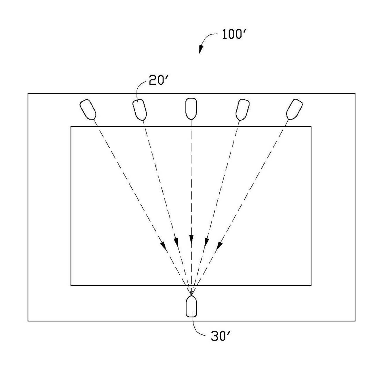
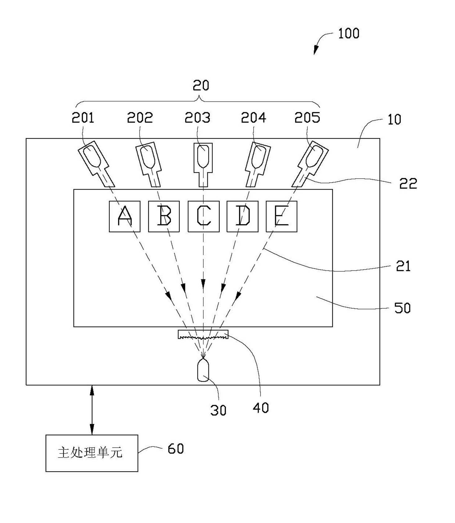
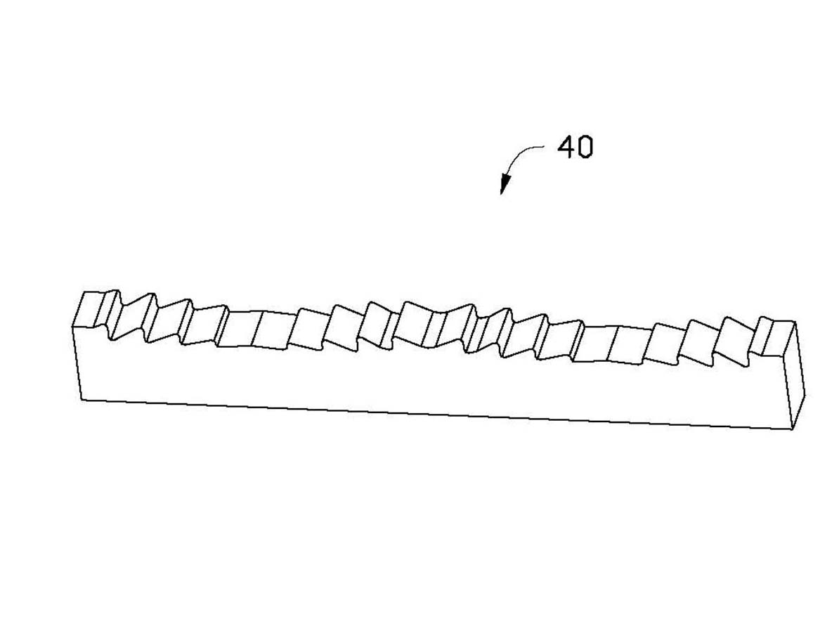
[0017] see figure 2 , the present invention provides a touch device 100 , which includes a plurality of frames 10 , a plurality of emitters 20 , a receiver 30 , a composite optical lens 40 , a display screen 50 and a main processing unit 60 . Wherein, the plurality of emitters 20 are arranged on the frame 10 of at least one side of the display screen 50, the receiver 30 and the composite optical lens 40 are arranged on the frame 10 opposite to the plurality of emitters 20, the composite optical The lens 40 is disposed on the same frame as the receiver, and is located directly in front of the receiver 30 .

[0018] When the touch device 100 is turned on, the main processing unit 60 controls the plurality of emitters 20 to emit infrared light 21 sequentially. In order to facilitate concentrated transmission of light and make it easier for the receiver 30 to receive the light 21 emitted by each emitter 20, in this embodiment, the plurality of emitters 20 are placed toward the p...


PUM


Abstract

The invention relates to a compound optical lens which is applied to a touch-control device, wherein the touch-control device comprises a plurality of emitters and a receiver which is arranged opposite to the emitters; the compound optical lens is arranged in front of the receiver and is provided with a plurality of lens parts and a plurality of mutually parallel optical axes corresponding to the lens parts; the lens parts are corresponding to the emitters one by one; the width proportion of each lens part in the whole compound optical lens is correspondingly arranged according to the distance and angle between the corresponding emitter and the compound optical lens; and the infrared light emitted from each emitter is transmitted to the receiver after having the optical action by passing through the corresponding lens part. By using the touch-control device using the compound optical lens, the lights emitted by the emitters at different positions and directions can be excellently gathered and the intensities of the signals received by the receiver can be kept consistently.

Description

technical field [0001] The invention relates to a composite optical lens and a touch device using the composite optical lens. Background technique [0002] Such as figure 1 As shown, it is a schematic diagram of the many-to-one structure adopted in the current optical touch device 100'. The optical touch device 100' adopts a structure in which multiple signal transmitters 20' are arranged opposite to one receiver 30'. In this many-to-one structure, due to the angle and Inconsistent distances, resulting in the intensity of light signals emitted by some transmitters 20' farther away from the receiver 30' reaching the receiver 30' may not reach the receiving threshold of the receiver 30', or some angles relative to the receiver 30' The optical signal emitted by the larger transmitter 20' cannot be received by the receiver 30', which will adversely affect the processing result of the received signal. Contents of the invention [0003] In view of this, it is necessary to pro...

Claims


Application Information

Patent Timeline
Patent Type & Authority Applications(China)
IPC IPC(8): G02B3/00G06F3/042G02B3/08
CPCG02B3/08G06F3/0421
Inventor LIANG KUNYANG CHANGJIANGYUAN JIAN
Owner HONG FU JIN PRECISION IND (SHENZHEN) CO LTD
Why Eureka
Try Eureka