
Plasma display panel

一种等离子体、显示面板的技术,应用在交流电等离子显示板、气体放电电极、固体阴极零部件等方向,能够解决放电效率降低、空间小、放电电压升高等问题

Inactive Publication Date: 2006-03-08
SAMSUNG SDI CO LTD
View PDF0 Cites 0 Cited by
  • Summary
  • Abstract
  • Description
  • Claims
  • Application Information

AI Technical Summary

Problems solved by technology

Thus, the space between the virtual barrier and the sealing member becomes too small, so that satisfactory air discharge cannot be obtained through the space between the virtual barrier and the sealing member
As a result, impurities remain in the panel, causing discharge voltage to rise, causing misdischarge, which leads to a decrease in discharge efficiency

Method used


Image

  • Plasma display panel
  • Plasma display panel
  • Plasma display panel

Examples


Embodiment Construction

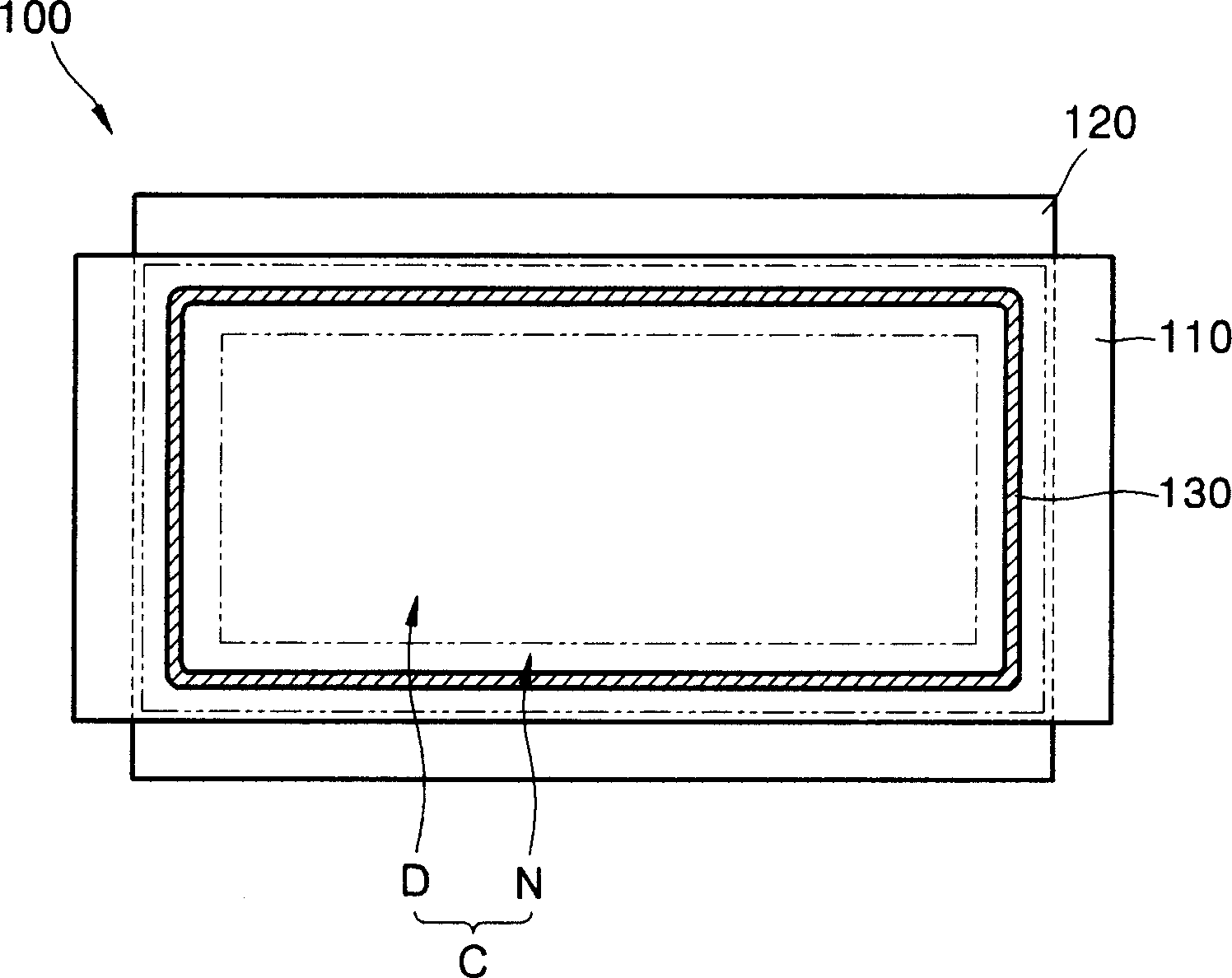
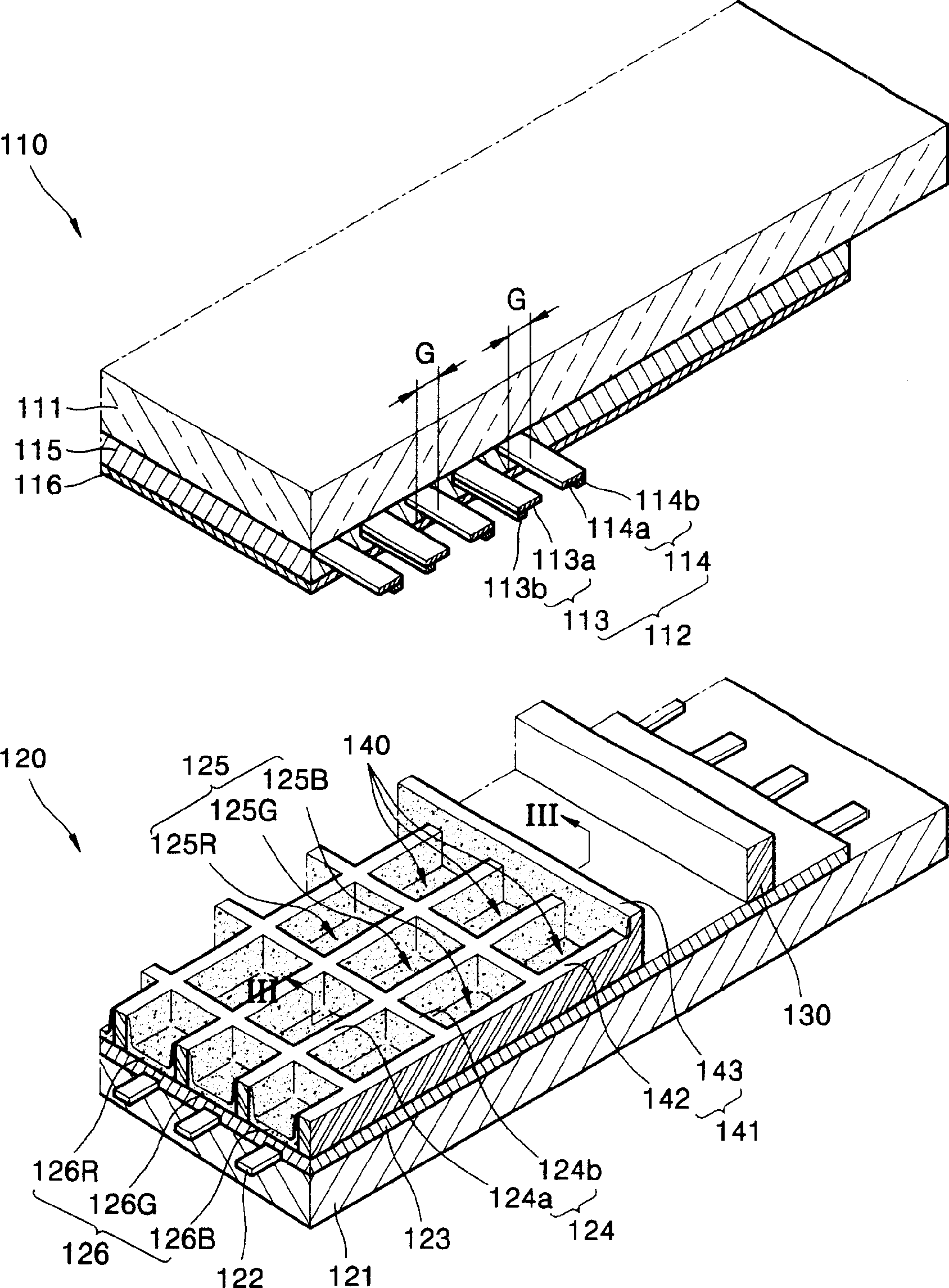
[0025] Referring now to the accompanying drawings, figure 1 is a plan view of a plasma display panel 100 according to an embodiment of the present invention. figure 1 The plasma display panel 100 includes an upper panel 110 and a lower panel 120 connected to and parallel to the upper panel 110 . A common area (C) where the upper panel 110 and the lower panel 120 overlap each other may be divided into a display area (D) and a virtual area (N). Here, the display area (D) is located at the center of the public area (C) and is a place where images are generated and displayed, while the virtual area (N) is set along the edge or periphery of the public area (C) and is not set at the place where images are displayed . In the dummy area (N), a sealing member 130 such as frit is provided along the edges to connect and seal the upper and lower panels 110 and 120 together.

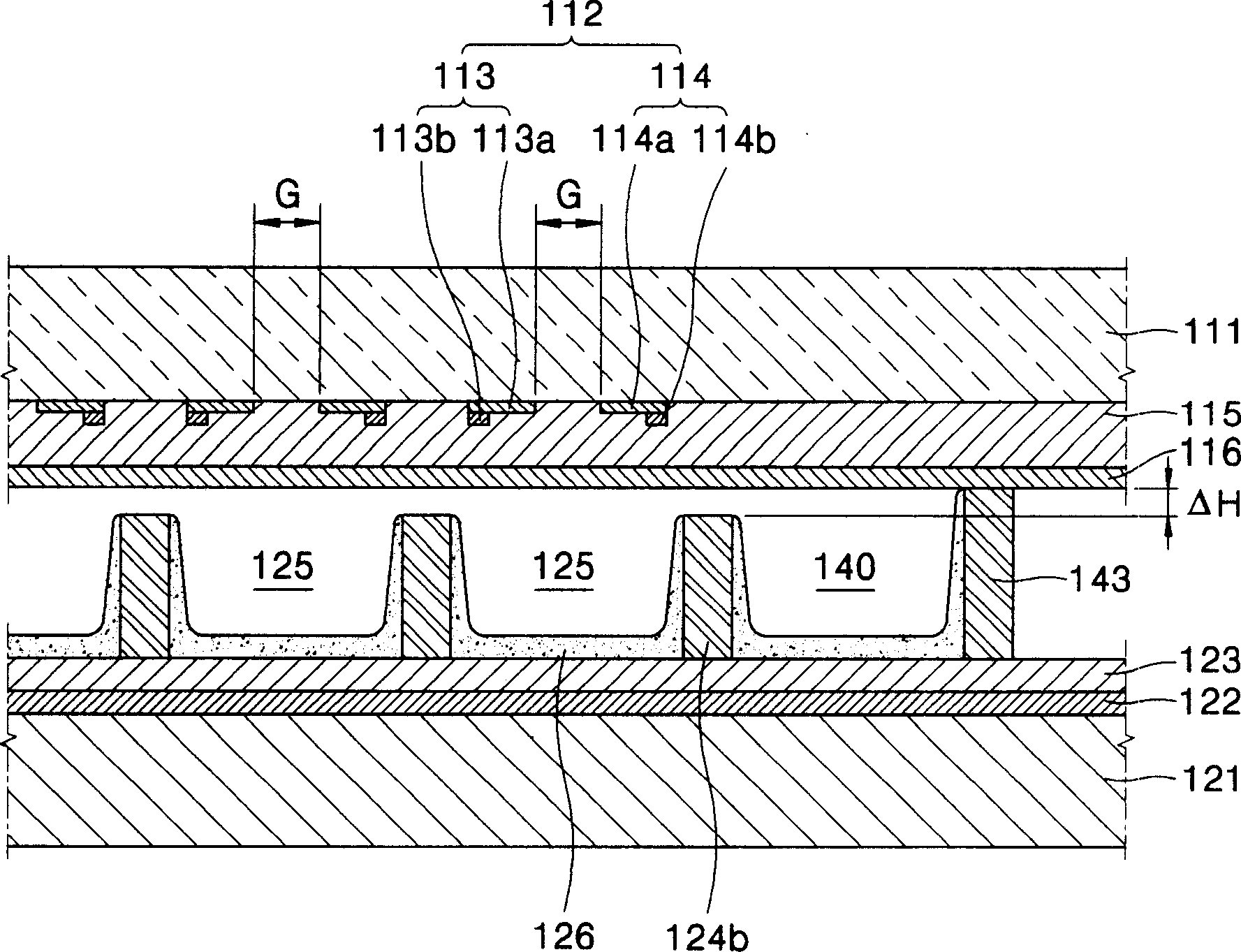
[0026] now refer to figure 2 and image 3 , figure 2 yes figure 1 A partial perspective view of the displ...


PUM


Abstract

A plasma display panel design having a display area and a peripheral area surrounding the display area. Within the display area are discharge cells, and within the peripheral area are dummy cells that serve as a location where fluorescent paste is injected onto in an early stage of making the display, enabling the injection amount and injection speed from a nozzle to stabilize before the fluorescent material is deposited into the discharge cells. A surface area that the fluorescent material is deposited on in the peripheral area is increased to provide for a more rapid stabilization of the injection pressure and injection amount of the paste in the making of the display. A sufficient gap is present between a sealant and the dummy structure so that air and foreign matter can be expelled.

Description

technical field [0001] The present invention relates to plasma display panels, and more particularly, to plasma display panels having an improved structure in which sufficient gas discharge can be achieved without sacrificing discharge efficiency. Background technique [0002] Plasma display panels are recently replacing cathode ray tubes (CRTs) as devices for displaying images. In a plasma display panel, a discharge gas is filled between two substrates supporting a plurality of electrodes, a discharge voltage is applied to the electrodes in the panel to generate ultraviolet rays, and the ultraviolet rays excite phosphor layers in a predetermined pattern to generate visible images. [0003] The plasma display panel may be classified into a direct current (DC) type and an alternating current (AC) type. In a DC type plasma display panel, electrodes are exposed to a discharge space so that electric charges directly move between corresponding electrodes. In the AC type plasma ...

Claims


Application Information

Patent Timeline
Patent Type & Authority Applications(China)
IPC IPC(8): H01J17/49H01J17/04H01J17/16H01J11/22H01J11/24H01J11/34H01J11/36H01J11/42
CPCH01J2211/363H01J2211/368H01J2211/48H01J11/12H01J11/36H01J11/42H01J2211/54
Inventor 金镛埈姜太京金基正
Owner SAMSUNG SDI CO LTD
Learn More