Linear actuator

A technology of linear actuators and coils, applied to magnetic objects, machines/engines, electromechanical devices, etc., can solve the problems of difficult to compact devices, inability to manufacture at low cost, and limited scope of use, reducing power consumption, The effect of smooth magnetic transmission and overall compactness of the device

Inactive Publication Date: 2006-03-15
NIPPON PULSE MOTOR CO LTD
View PDF1 Cites 32 Cited by
  • Summary
  • Abstract
  • Description
  • Claims
  • Application Information

AI Technical Summary

Problems solved by technology

[0006] As a result, it is difficult to set a large magnetic gap (about 5 to 30 mm) to vibrate in a long stroke, and not only the above-mentioned expensive stator magnet M is required, but also it is difficult to compact the device, and the device itself becomes larger and cannot be manufactured at low cost. , its use is limited

Method used


Image

  • Linear actuator
  • Linear actuator
  • Linear actuator

Examples


Embodiment Construction

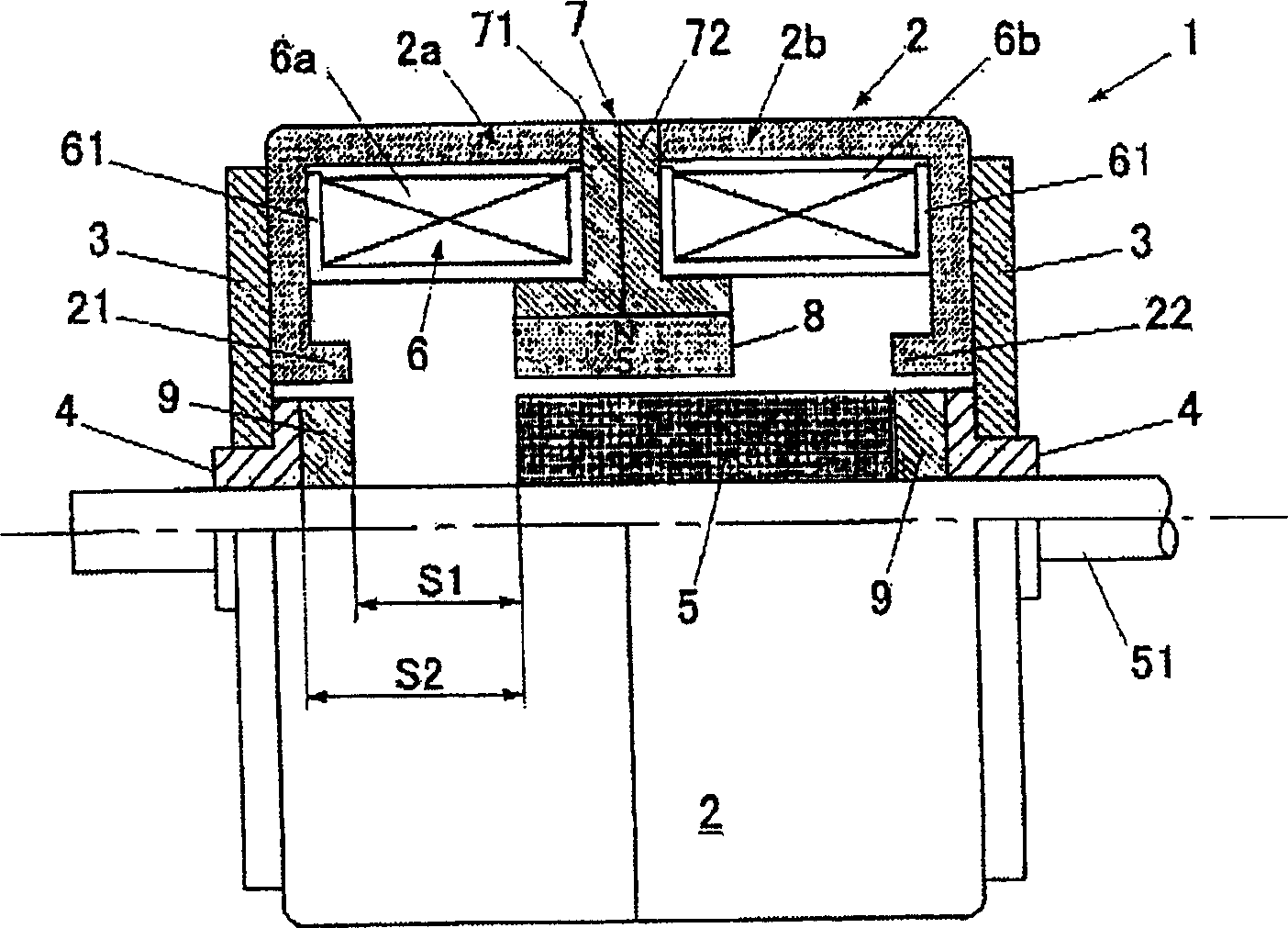
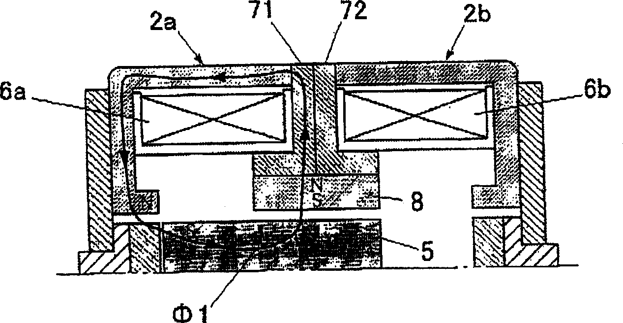
[0017] A linear actuator exemplified by an embodiment of the present invention as a best mode will be described in detail below with reference to the accompanying drawings. figure 1 is the half-section structure diagram of the linear actuator, figure 2 This is an explanatory diagram of the magnetic circuit of the coil. As shown in the figure, reference numeral 1 is a linear actuator including a yoke 2 composed of a cylindrical body forming a main body of the linear actuator and iron, magnetic stainless steel, etc. forming a magnetic circuit, Bearings 4, 4 provided at the centers of flanges 3, 3 arranged on both sides of the yoke 2 and a mover 5 having a shaft portion 51 mounted on the bearings 4 so as to be movable in the axial direction, Coils 6 ( 6 a , 6 b ) wound on a resin bobbin 61 provided on the inner wall of the yoke are arranged in the yoke 2 , and stator magnets 8 made of permanent magnets are arranged between the coils 6 and the mover 5 .

[0018] Said coil 6 is...


PUM


Abstract

The present invention provides a linear actuator capable of propagating magnetic force of a stator magnet (8) within a yoke (2) in a smooth manner so as to form a superior constant magnetic field to concentrate the flux density on magnetic pole pieces (21, 22), even if the stator magnet (8) is not provided with strong magnetic force, the stator is capable of efficiently providing stoppage keep in a non-excitation state and magnetic thrust brought by excitation to a moving member (5); the linear actuator is capable of corresponding to not only the short stroke, but also the long stroke. A coil (6) is configured into split coils so as to retain excitation function, and a magnetic path body (7) for connecting the stator magnet (8) and the yoke (2) is provided between the split coils (6a, 6b); and magnetic force of the stator magnet (8) is directly transmitted to the yoke (2) via the magnetic path body (7).

Description

technical field [0001] The present invention relates to an electromagnetic linear actuator, in particular to a linear actuator capable of forming a good magnetic circuit in a magnetic yoke. Background technique [0002] Such linear actuators are typically used to continuously vibrate the piston of an air compressor, the blade of a razor, and the like. In these vibrations, it is necessary to give a strong reciprocating driving force to the mover and move it in accordance with the vibration resistance due to the application. [0003] Conventionally, as disclosed in Japanese Patent Application Publication No. 8-510361, a stator magnet (permanent magnet) is disposed in the center of a yoke having a substantially concave cross section together with a coil, and a mover having approximately the same width as the stator magnet is embedded in the magnetic yoke. Inside the yoke, a 1mm-wide inclined magnetic gap is formed between the two pole pieces of the yoke, and vibrates continuou...

Claims


Application Information

Patent Timeline
Patent Type & Authority Applications(China)
IPC IPC(8): H01F7/16
CPCH02K33/12H01F2007/1692F04B35/04H01F7/1615
Inventor 佐藤修治
Owner NIPPON PULSE MOTOR CO LTD
Why Eureka
Try Eureka