

Key switch structure
A switch and structure technology, applied in the direction of electrical switches, electrical components, circuits, etc., can solve the problem of difficult to achieve long stroke, and achieve the effect of increasing the stroke length
- Summary
- Abstract
- Description
- Claims
- Application Information
AI Technical Summary
Problems solved by technology
Method used
Image

Examples
Embodiment
[0027] (constitute)
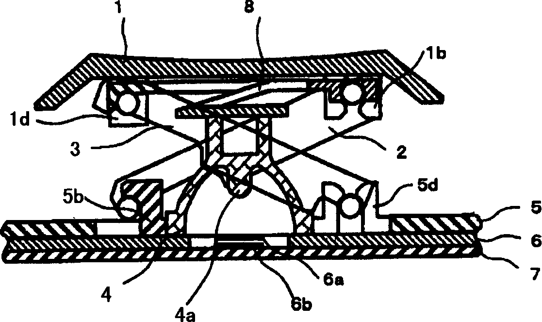
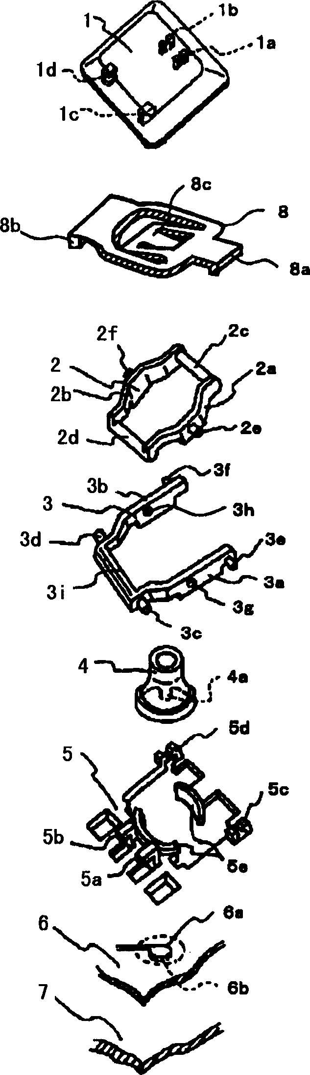
[0028] figure 1 It is a structural diagram showing the key switch of the embodiment, figure 2 It is an exploded perspective view showing the push switch of the embodiment.
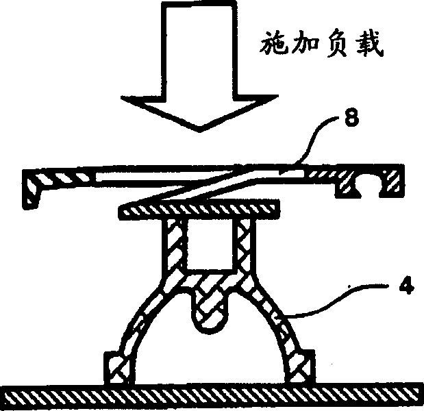
[0029] The key switch of the embodiment is composed of a key tip 1 , a first link member 2 , a second link member 3 , a cup rubber 4 , a case 5 , a contact piece 6 , a base plate 7 and a spring portion 8 .
[0030] On the key top end portion 1, there are provided rotation support portions 1a, 1b that rotatably support one end of the first link member 2, and figure 1 In the horizontal direction, the sliding support portions 1c, 1d at one end of the second link member 3 are slidably supported.
[0031] As shown in the figure, the spring part 8 is formed by, for example, stamping and bending an aluminum plate to provide fixing parts 8a, 8b and a spring 8c. In this way, the fixing portion 8a is disposed on the first connecting rod 2c described later of the first link member 2, and ...
PUM
 Abstract
Description
Claims
Application Information