

Double-speed segmented contact of ultrahigh voltage
An ultra-high voltage and switching technology, which is applied in the field of double-speed breaking contacts of ultra-high voltage switches, can solve the problems affecting the service life of equipment, power consumption, and increase production costs, so as to reduce the volume of the operating mechanism, shorten the arcing time, and prolong the service life. Effect
- Summary
- Abstract
- Description
- Claims
- Application Information
AI Technical Summary
Problems solved by technology
Method used
Image

Examples
Embodiment Construction
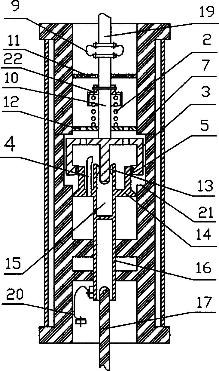
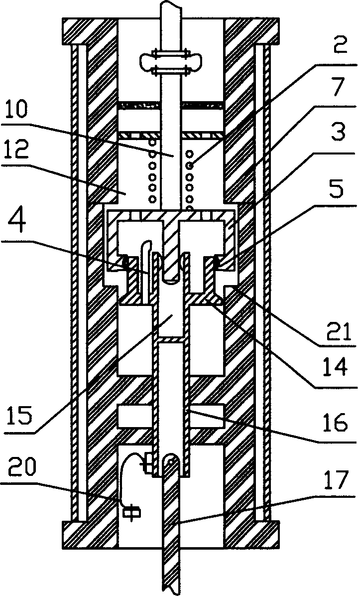
[0017] Such as figure 1 As shown, the UHV switch double-speed breaking contact of the present invention includes an insulating cylinder 7 and a static contact 3 arranged in the insulating cylinder 7, the static contact 3 and the insulating cylinder 7 are connected by a spring 2, and the static contact 3 There is a load static contact 5 on the contact surface with the moving contact 14, and the inner wall of the insulating cylinder 7 has a blocking step 21 for preventing the movement of the static contact 3. The static contact 3 has a disc-shaped static contact base with a through hole, the center of the static contact base has a columnar arc-extinguishing contact, and multiple load static contacts 5 are distributed around the base ; Correspondingly, the moving contact 14 has a disc-shaped moving contact base, the moving contact base has an arc blowing tube 4 that runs through it, and the upper end of the arc blowing tube 4 faces the arc extinguishing contact of the static cont...
PUM
 Abstract
Description
Claims
Application Information