Galvanic battery with detection unit
A technology of battery pack and detection unit, which is applied in the direction of measuring electricity, secondary batteries, measuring electrical variables, etc., can solve the problems of non-battery faults that cannot be detected and too many connections
- Summary
- Abstract
- Description
- Claims
- Application Information
AI Technical Summary
Problems solved by technology
Method used
Image

Examples
Embodiment 1
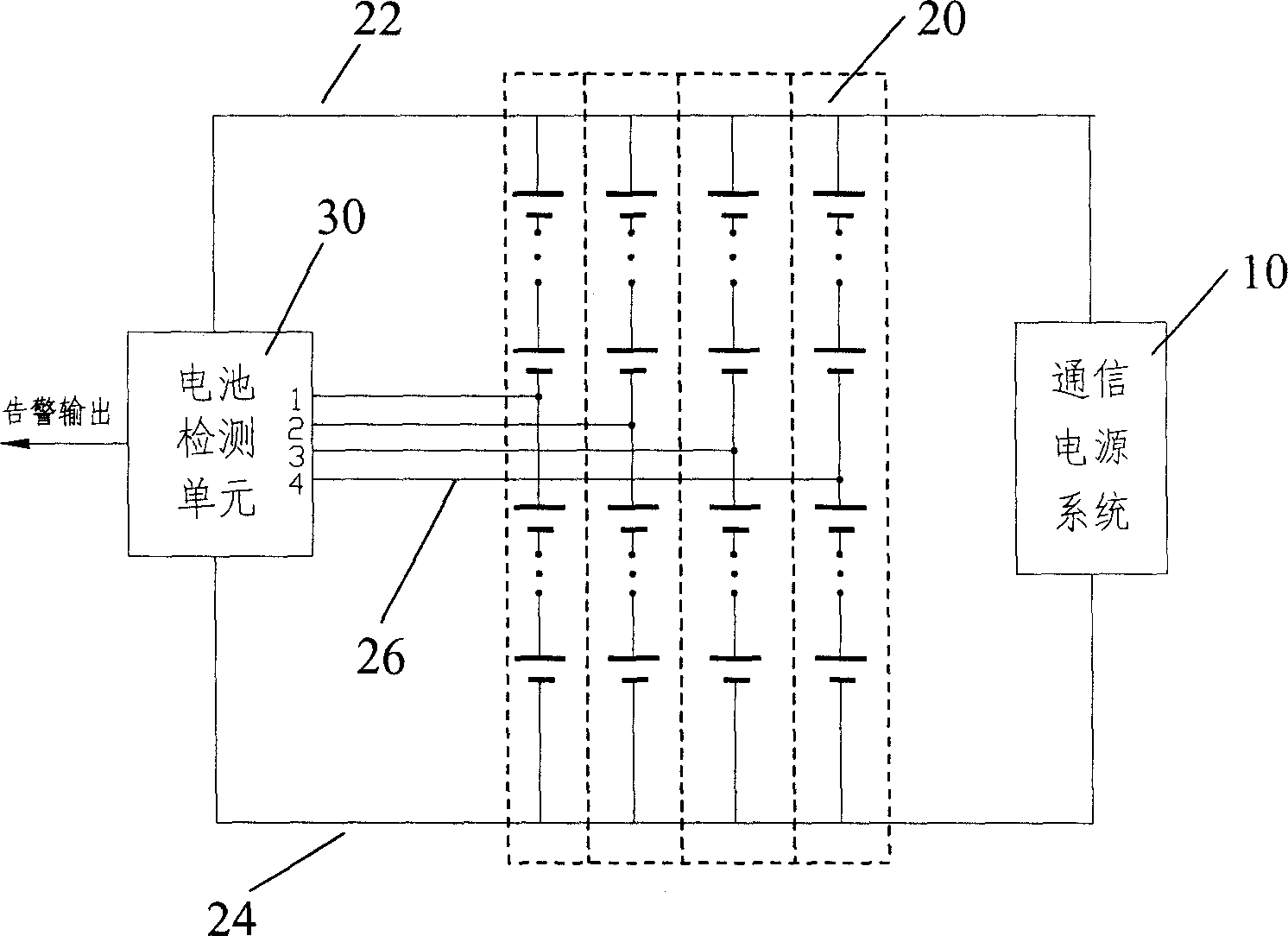
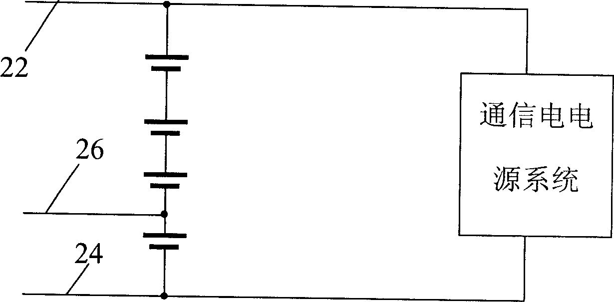
[0032] Figure 2A It is a schematic diagram of the principle of Embodiment 1, which includes a battery detection unit 30 and one or more groups of battery subgroups 20 connected in parallel, wherein each battery subgroup 20 includes a plurality of single batteries connected in series; the battery detection unit 30 uses To detect the state of the battery subgroup according to the detection point voltage of each battery subgroup 20, it includes one or more detection voltage input terminals, which are respectively connected to the detection point voltage output terminals 26 of each battery subgroup; the detection point is set at At the midpoint of a battery subpack (a battery subpack contains an even number of cells, so there can be a true midpoint). At this time, each battery sub-group only needs to connect at least three wires.
[0033] Figure 3A Shown is a schematic block diagram of the battery detection unit 30 of this embodiment, which includes a detection point ideal vol...
Embodiment 2
[0046] like Figure 2B , 2C As shown, each battery sub-group 20 still includes only one detection point, which is set at a node located close to the midpoint of the battery sub-group and far away from the terminal voltage output end of the battery group, rather than strictly located at the midpoint (when the single battery When the number is an odd number, there will be no strict midpoint, and this embodiment is especially useful).
[0047] According to the first and second embodiments, real-time detection of the storage battery can be realized with the least wiring, and the reasons are explained as follows:
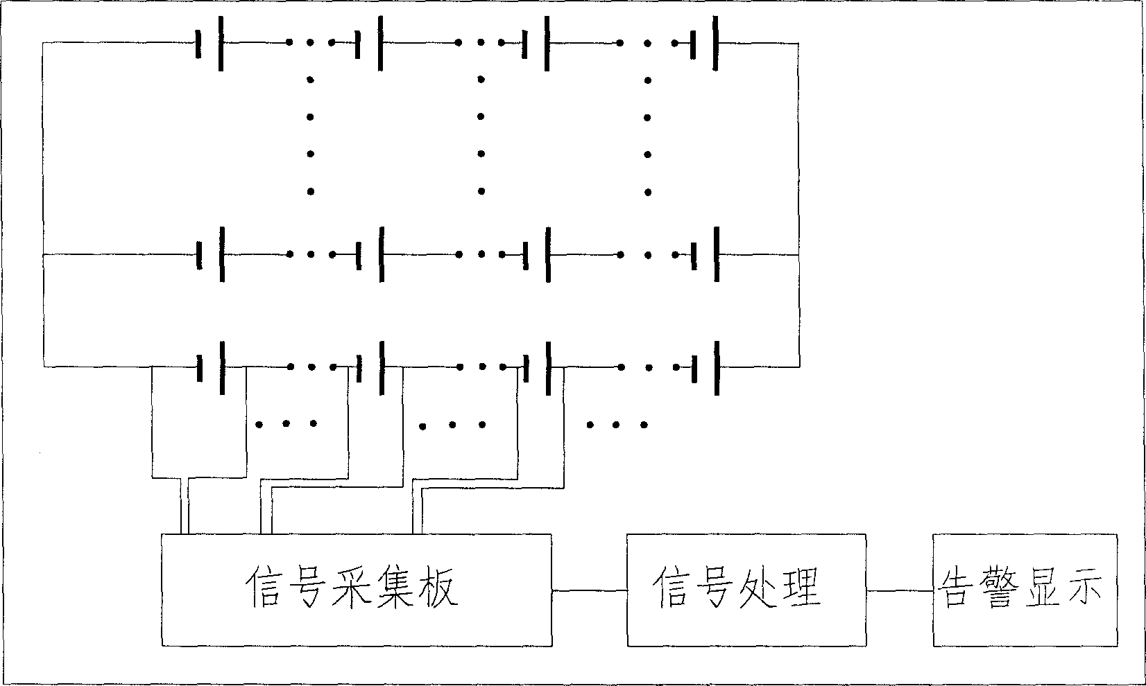
[0048] (1) Since the battery pack works in parallel with one or more battery sub-groups and the communication power supply, the terminal voltage of one of the battery sub-groups can still remain unchanged when a fault occurs in one of the battery sub-groups, so it is impossible to simply detect the terminal voltage of the battery pack To achieve the detection purpose. ...
Embodiment 3
[0053] like Figure 2D As shown, in each battery subgroup, there is more than one detection point, which is set at the node of the series connection of the battery cells in the battery subgroup. At least two battery cells are spaced between at least one of the voltage output terminals 22 , 24 . The advantage of doing this is that when a fault occurs, the location of the fault in the battery sub-group can be further located, instead of only locating which battery sub-group has failed as in the first embodiment.
[0054] But as before, the purpose of battery testing is to find faults. Once a fault is found, the rest of the problems—determining the fault location and follow-up disposal—are easy to deal with. Therefore, in comparison, finding a fault is much more important than locating the fault location, and the first and second embodiments achieve this with the least wiring. It can be seen that each of the three embodiments has its unique advantages.
PUM
 Abstract
Description
Claims
Application Information
 - R&D
- Intellectual Property
- Life Sciences
- Materials
- Tech Scout
- Unparalleled Data Quality
- Higher Quality Content
- 60% Fewer Hallucinations
Browse by: Latest US Patents, China's latest patents, Technical Efficacy Thesaurus, Application Domain, Technology Topic, Popular Technical Reports.
© 2025 PatSnap. All rights reserved.Legal|Privacy policy|Modern Slavery Act Transparency Statement|Sitemap|About US| Contact US: help@patsnap.com