Liquid storing tank for air conditioner

A liquid storage tank and air conditioner technology, which is applied in the field of air conditioners, can solve the problems of different lubricating oil amount of refrigerant pipe 16 and wear of internal running parts, etc.

Inactive Publication Date: 2006-03-29
LG ELECTRONICS (TIANJIN) APPLIANCES CO LTD
View PDF0 Cites 3 Cited by
  • Summary
  • Abstract
  • Description
  • Claims
  • Application Information

AI Technical Summary

Problems solved by technology

[0010] However, the liquid storage tank 10 that supplies refrigerant to a plurality of compressors is provided with a plurality of refrigerant pipes 16 inside the main body 12. Since the holes 16a of the refrigerant pipes 16 are not arranged at the same height, it will cause the refrigerant to flow into the pipes 16. The amount of lubricating oil is different
Because the amount of lubricating oil flowing into each refrigerant pipe 16 is different, it will cause a certain compressor lubricating oil, and the lack of lubricating oil in the compressor will cause serious wear and tear of the internal operating parts.

Method used


Image

  • Liquid storing tank for air conditioner
  • Liquid storing tank for air conditioner
  • Liquid storing tank for air conditioner

Examples


Embodiment Construction

[0034] Embodiments of the present invention will be further described below in conjunction with the accompanying drawings.

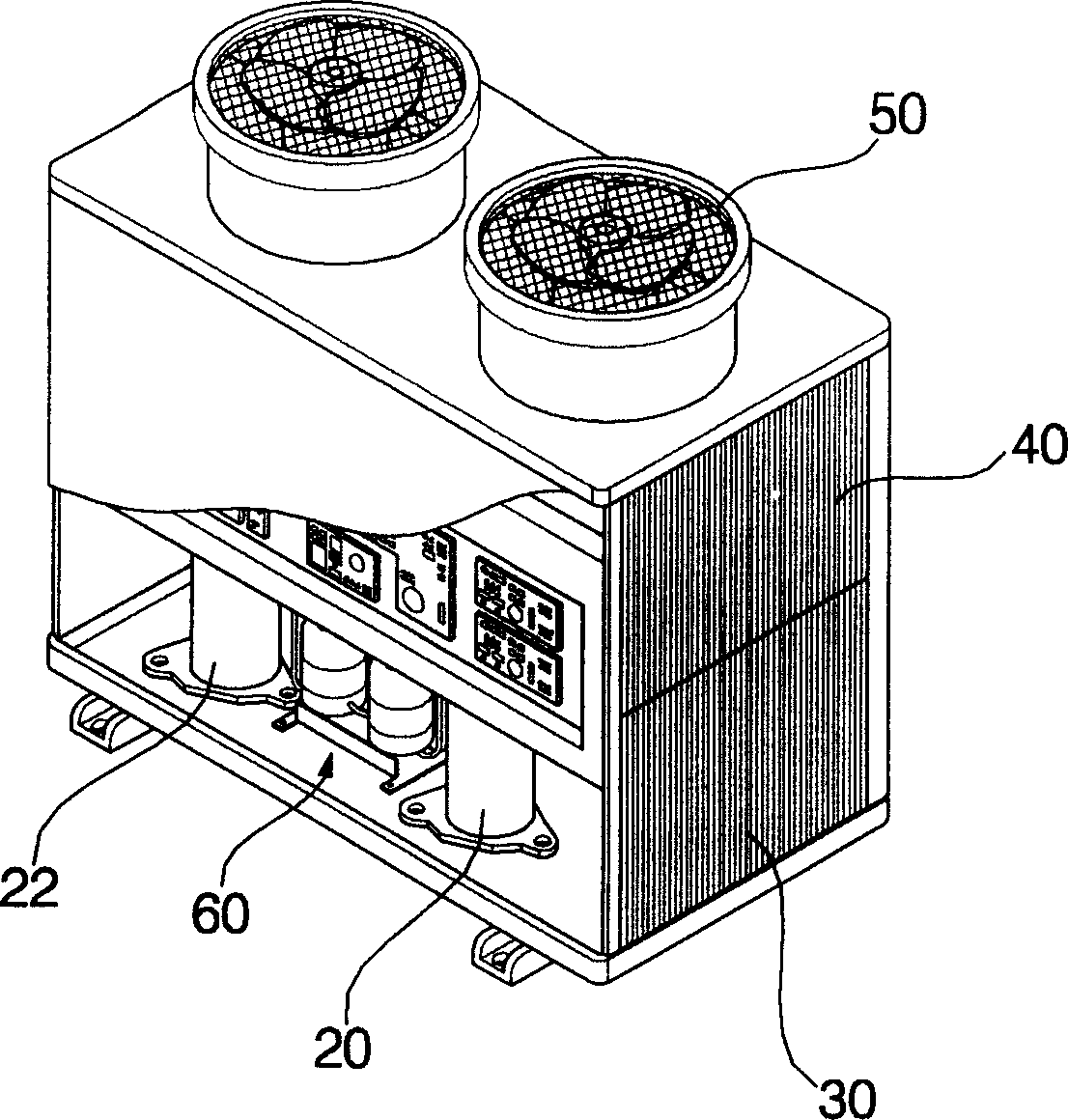
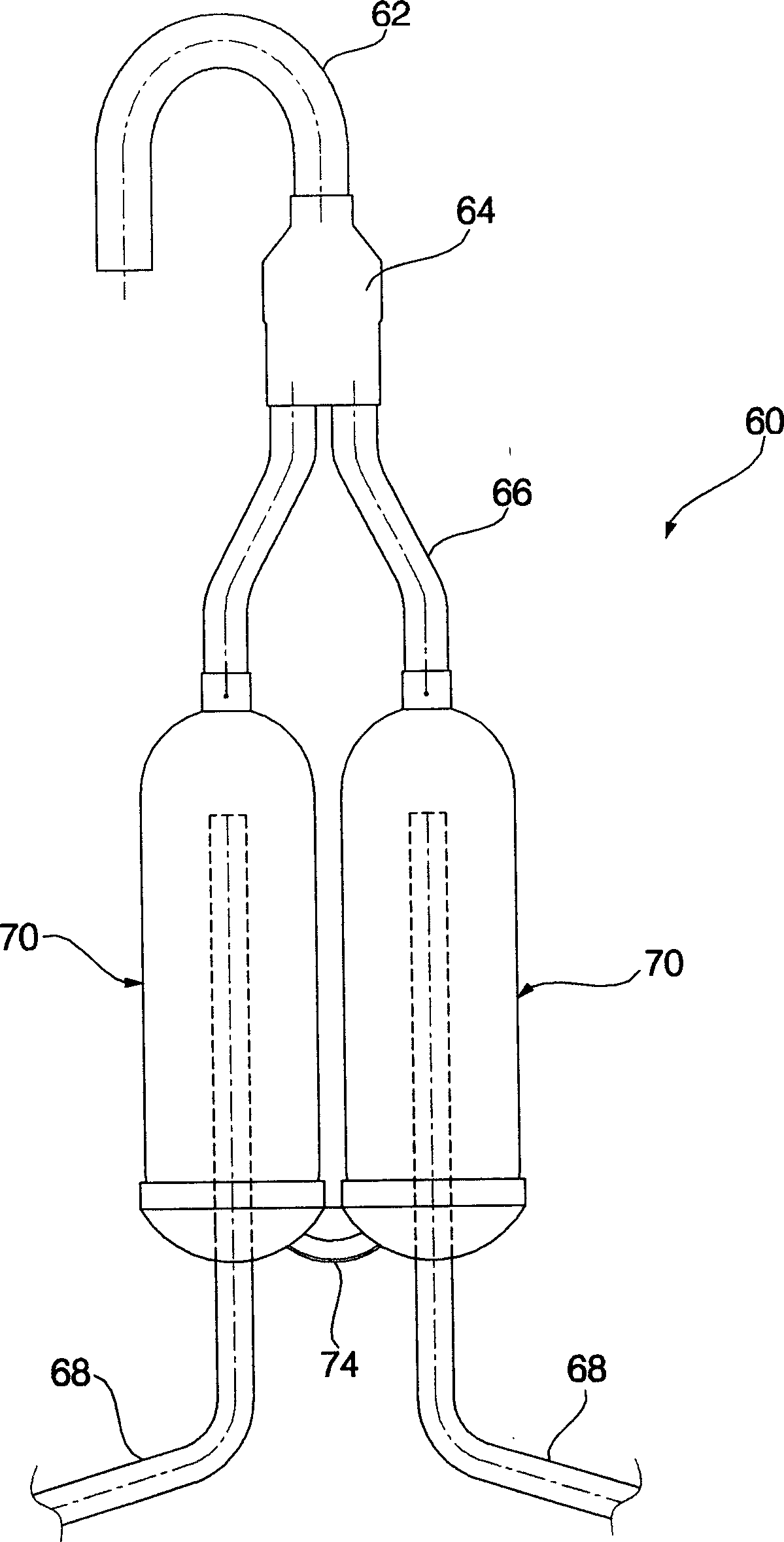
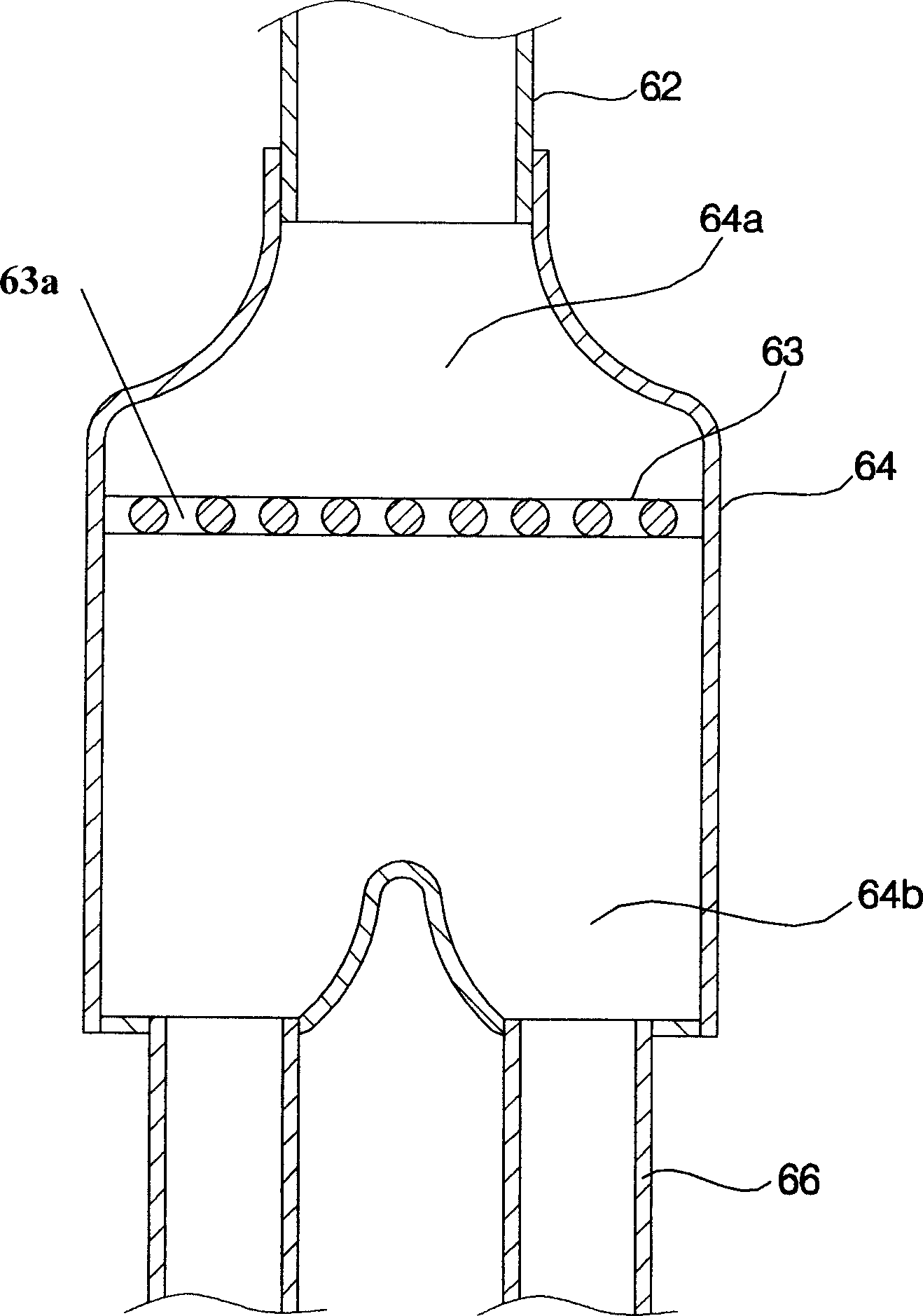
[0035] figure 1 It is a partially cut-away three-dimensional schematic diagram of the outdoor unit of the air conditioner of the present invention; figure 2 yes figure 1 Schematic diagram of the medium storage tank structure; image 3 yes figure 2 Partial cross-sectional enlarged view of the middle distributor; Figure 4 yes figure 2 Enlarged cutaway view of the main body.

[0036] Such as Figure 1 to Figure 4 As shown, the outdoor unit of the air conditioner of the present invention is composed of a casing 40 that constitutes an external shape; a plurality of compressors 20, 22 that compress the refrigerant; a liquid storage tank 60 that supplies the refrigerant to the compressors 20, 22; 22 is composed of an outdoor heat exchanger 30 for exchanging heat between refrigerant and air; and a blower 50 for discharging air inside the cabinet 40 ...


PUM


Abstract

The present invention discloses a liquor storage tank for air conditioning machine. It includes supply pipe connected with outdoor heat exchanger, several main bodies for supplying refrigerant and lubricating oil to every compressor and distributor which is placed under the supply pipe and is used for uniformly supplying refrigerant and lubricating oil to several main bodies. Besides, said invention also provides the working principle of said liquor storage tank.

Description

technical field [0001] The present invention relates to an air conditioner, in particular to a liquid storage tank for the air conditioner. Background technique [0002] Generally, an air conditioner is an outdoor unit connected to multiple indoor units, and the multiple indoor units are used for cooling or heating. [0003] Figure 5 It is a partially cut-away three-dimensional schematic diagram of an outdoor unit of an air conditioner in the prior art. [0004] Such as Figure 5 As shown, the air conditioner in the prior art is composed of an indoor unit 1 and an outdoor unit 2; a refrigerant pipe 3 connecting the indoor unit and the outdoor unit and making the refrigerant flow. [0005] The existing outdoor unit 2 is a compressor 4 that compresses the refrigerant into a high-temperature and high-pressure state; the refrigerant compressed by the compressor 4 is supplied to the outdoor heat exchanger 5 or a four-way valve (not shown) of the indoor heat exchanger; The outd...

Claims


Application Information

Patent Timeline
Patent Type & Authority Applications(China)
IPC IPC(8): F25B43/00F24F13/00
Inventor 金柾勋
Owner LG ELECTRONICS (TIANJIN) APPLIANCES CO LTD
Why Eureka
Try Eureka