Platemaking method and platemaking apparatus

A printing plate and modulator technology, which is applied in the field of plate making of printing plates and plate making devices of printing plates, can solve the problems of high power and long time of printing plates, etc.

Inactive Publication Date: 2006-04-05
DAINIPPON SCREEN MTG CO LTD
View PDF1 Cites 29 Cited by
  • Summary
  • Abstract
  • Description
  • Claims
  • Application Information

AI Technical Summary

Problems solved by technology

[0004] At this time, since the engraving of the recording material by the laser beam requires relatively large power, there is a problem that it takes a long time to make the printing plate.

Method used


Image

  • Platemaking method and platemaking apparatus
  • Platemaking method and platemaking apparatus
  • Platemaking method and platemaking apparatus

Examples


Embodiment Construction

[0032] Embodiments of the present invention will be described below based on the drawings.

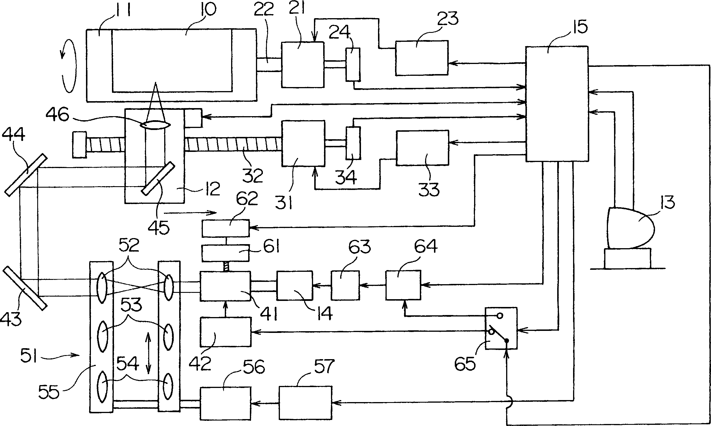
[0033] In the following description, first, the fine engraving process of engraving up to the maximum depth dp by irradiating the flexible photosensitive material 10 with the fine engraving beam L1 at the fine engraving pixel pitch pp, and the coarse engraving beam L2 at the coarse engraving pixel pitch pc irradiates the flexible photosensitive material 10 to engrave until the rough engraving step of the embossed depth d. The first feature of the present invention, which shortens the plate making time by performing engraving in two steps, will be described. The second feature of the present invention, which shortens the plate-making time while maintaining high plate-making accuracy, will be described.

[0034] figure 1 It is a block diagram showing the outline of a laser engraving machine as a plate making device of a relief printing plate according to the present invention.

[0035]...


PUM


Abstract

The invention provides a plate making method of a printing plate and the plate making device of a print plate. Engraving is conducted by a precise engraving process and a rough engraving process. The precise engraving process uses precise engraving beam of light with small beam diameter to irradiate the flexible photosensitive material at precise engraving pixel intervals. The engraving is conducted until the precise engraving beam of light reaches the maximum depth. The rough engraving process uses rough engraving beam with large beam diameter to irradiate the flexible photosensitive material at rough engraving pixel intervals which are larger than that of the precise engraving pixel intervals, and the engraving is conducted until the beam of light reaches the relief depth.

Description

technical field [0001] The present invention relates to a printing plate making method and a printing plate making apparatus for making a printing plate such as a letterpress printing plate such as a flexo plate or an intaglio printing plate such as an intaglio plate. Background technique [0002] Conventionally, a laser engraving machine described in US Pat. No. 5,327,167, for example, is known as a plate making apparatus for such a printing plate. This laser engraving machine manufactures relief printing plates by engraving the surface of the recording material by scanning the recording material with a laser beam emitted from a laser light source, and has: a laser light source; a modulator for modulating the laser beam emitted from the laser light source (modulator); a recording drum that rotates with a recording material mounted on its outer periphery; a recording material mounted on the outer periphery of the recording drum that is configured to be movable in a direction...

Claims


Application Information

Patent Timeline
Patent Type & Authority Applications(China)
IPC IPC(8): B41C1/05B41J2/455B41J29/38
Inventor 小川秀明
Owner DAINIPPON SCREEN MTG CO LTD
Why Eureka
Try Eureka