Vapor-compression refrigerant cycle system with ejector
A circulation system and high-pressure refrigerant technology, which is applied in the direction of irreversible cycle compressors, refrigerators, compressors, etc., can solve the problems of compressor lubricating oil shortage, lubricating oil return reduction, etc.
- Summary
- Abstract
- Description
- Claims
- Application Information
AI Technical Summary
Problems solved by technology
Method used
Image

Examples
no. 1 example
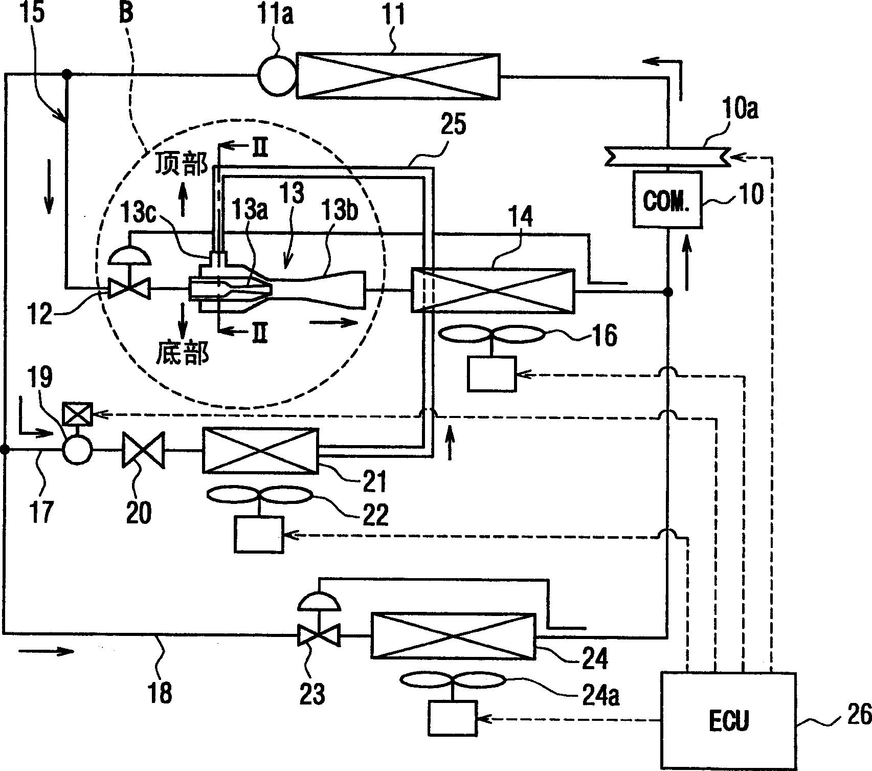
[0032] In the first embodiment, figure 1 The vapor-compression refrigerant cycle system with ejector shown in is commonly used for example in vehicle air conditioners. The vapor-compression refrigerant cycle system includes a main refrigerant path 15 in which the refrigerant flows from the discharge side of the compressor 10, the refrigerant cooler 11, the flow control valve 12, the ejector 13, the first evaporator 14, and the compressor 10 Sequential flow on the suction side.
[0033] In this embodiment, the vehicle engine drives and rotates the compressor 10 through a belt, an electromagnetic clutch 10a, and the like. The operation of the compressor 10 is switched and controlled by the electromagnetic clutch 10a. In this case, by controlling the on / off operation ratio of the compressor 10, the refrigerant discharge capability of the compressor 10 may be controlled.
[0034] The refrigerant cooler 11 cools the high-pressure refrigerant discharged from the compressor 10 by ...
no. 2 example
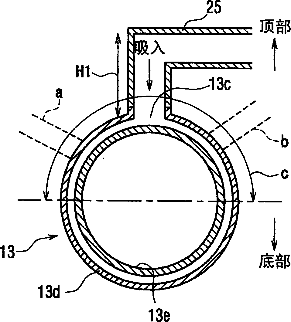
[0070] In the first embodiment described above, the refrigerant suction port 13c of the ejector 13 is provided at the upper portion of the casing 13d. However, in the second embodiment, as Figure 4 As shown in , the refrigerant suction port 13c is provided at the lower portion of the housing 13d, and an upstanding portion 25a extending in the vertical direction is formed in the downstream portion of the refrigerant suction pipe 25. The upright portion 25 a may vertically extend upward from the lowermost portion of the injector 13 by a predetermined height. exist Figure 4 In, H2 represents the height of the upright portion 25a extending vertically.
[0071] In the present embodiment, the lower tube portion downstream of the upright portion 25a in the refrigerant suction pipe 25 can be made shorter. Therefore, even when the refrigerant suction portion 13c is provided at the lower portion (for example, the bottom) of the housing 13d, the amount of lubrication remaining in th...
no. 3 example
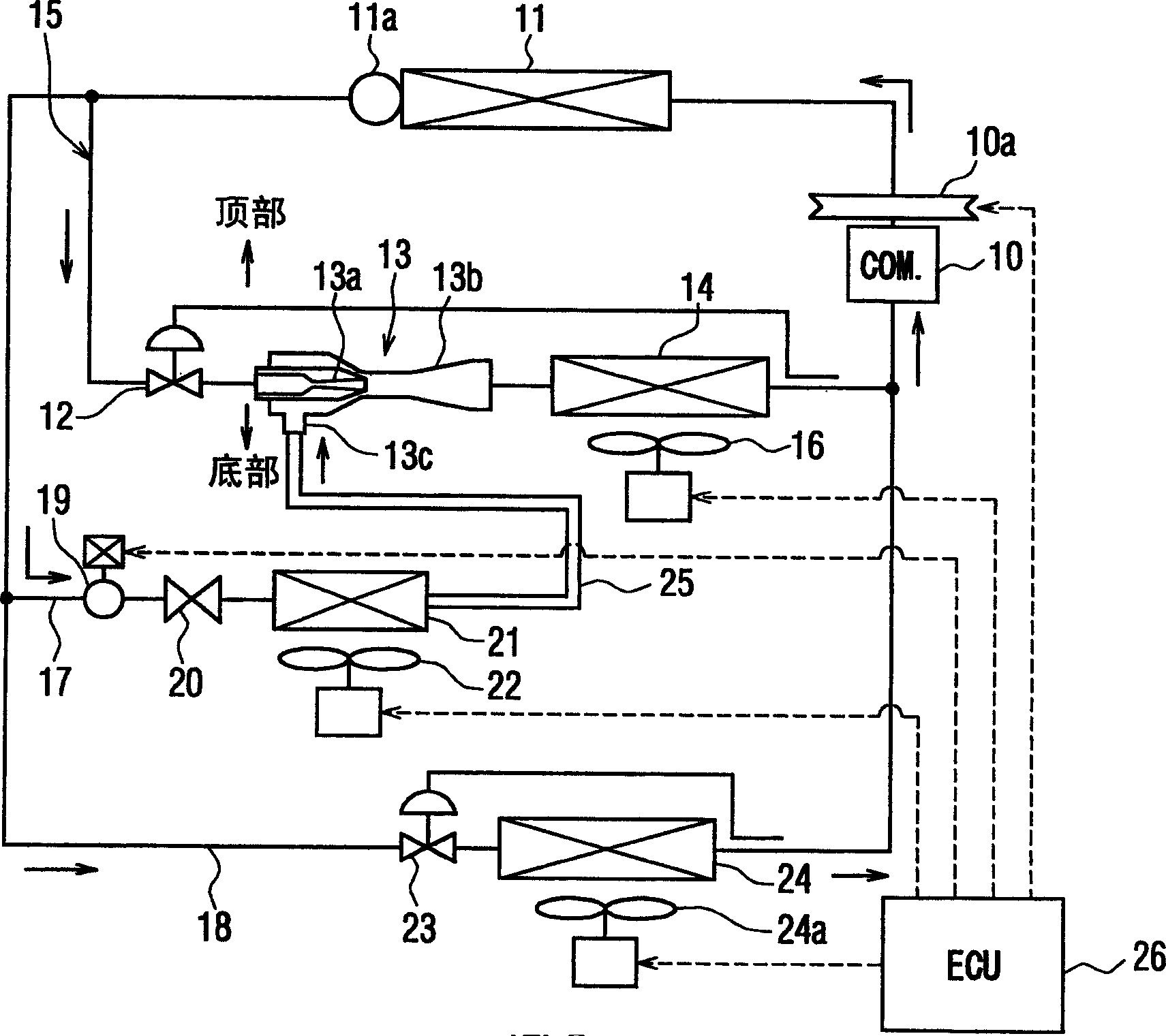
[0075] Figure 5 A vapor compression refrigerant cycle system of a third embodiment is shown. In the third embodiment, the solenoid valve 19 is not provided in the first branch passage 17 , and the refrigerant flowing out of the main refrigerant circulation path 15 flows into the second evaporator in the first branch part 17 after passing through the throttling mechanism 20 . Device 21. Therefore, when the compressor 10 operates, the refrigerant always flows into the second evaporator 21 in the first branch passage 17 .
[0076] Therefore, in the present embodiment, when the refrigerator function (refrigerator cooling operation) is stopped, the operation of the second blower 22 is also stopped. When the second blower 22 is stopped, the heat absorption of the refrigerant in the second evaporator 2 is very small, and a large amount of liquid refrigerant that has passed through the throttling mechanism 20 is sucked into the refrigerant suction port of the ejector 13 without bei...
PUM
 Abstract
Description
Claims
Application Information
 - R&D
- Intellectual Property
- Life Sciences
- Materials
- Tech Scout
- Unparalleled Data Quality
- Higher Quality Content
- 60% Fewer Hallucinations
Browse by: Latest US Patents, China's latest patents, Technical Efficacy Thesaurus, Application Domain, Technology Topic, Popular Technical Reports.
© 2025 PatSnap. All rights reserved.Legal|Privacy policy|Modern Slavery Act Transparency Statement|Sitemap|About US| Contact US: help@patsnap.com