Energy recovery apparatus and method for plasma display panel

An energy recovery and energy technology, applied in identification devices, static indicators, instruments, etc., can solve the problems of high manufacturing cost and high internal voltage, and achieve the effect of reducing manufacturing cost

Inactive Publication Date: 2006-04-05
LG ELECTRONICS INC
View PDF0 Cites 2 Cited by
  • Summary
  • Abstract
  • Description
  • Claims
  • Application Information

AI Technical Summary

Problems solved by technology

In addition, the fifth and sixth diodes D5 and D6 must have a fast response speed
Therefore, manufacturing costs are high due to the large number of components with fast response speed and high internal voltage used in the prior art

Method used


Image

  • Energy recovery apparatus and method for plasma display panel
  • Energy recovery apparatus and method for plasma display panel
  • Energy recovery apparatus and method for plasma display panel

Examples


Embodiment Construction

[0033] Hereinafter, preferred embodiments of the present invention will be specifically described with reference to the accompanying drawings.

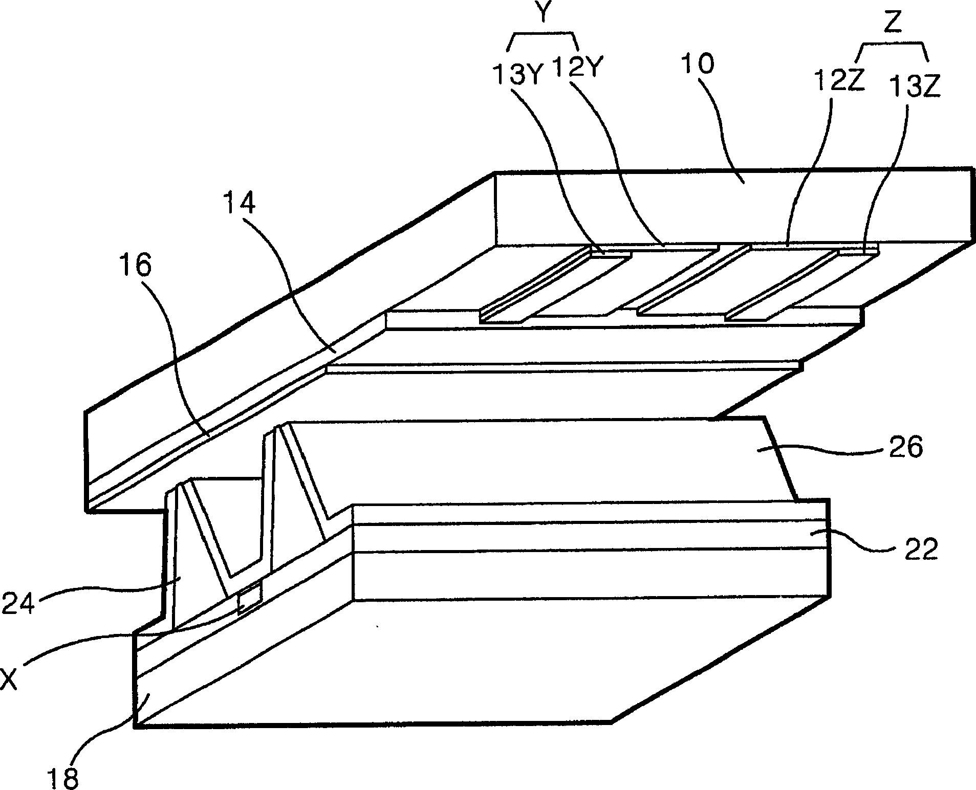
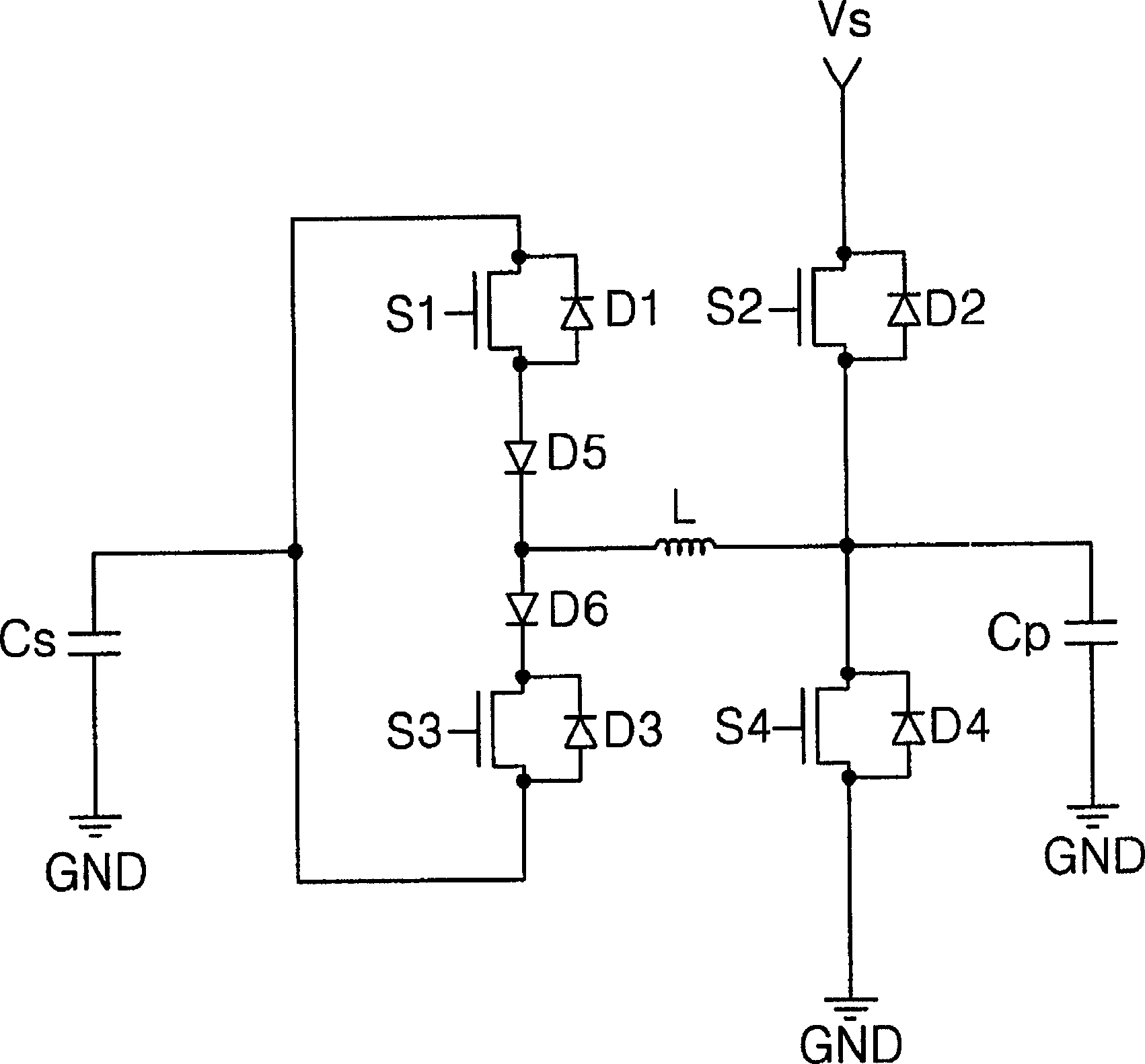
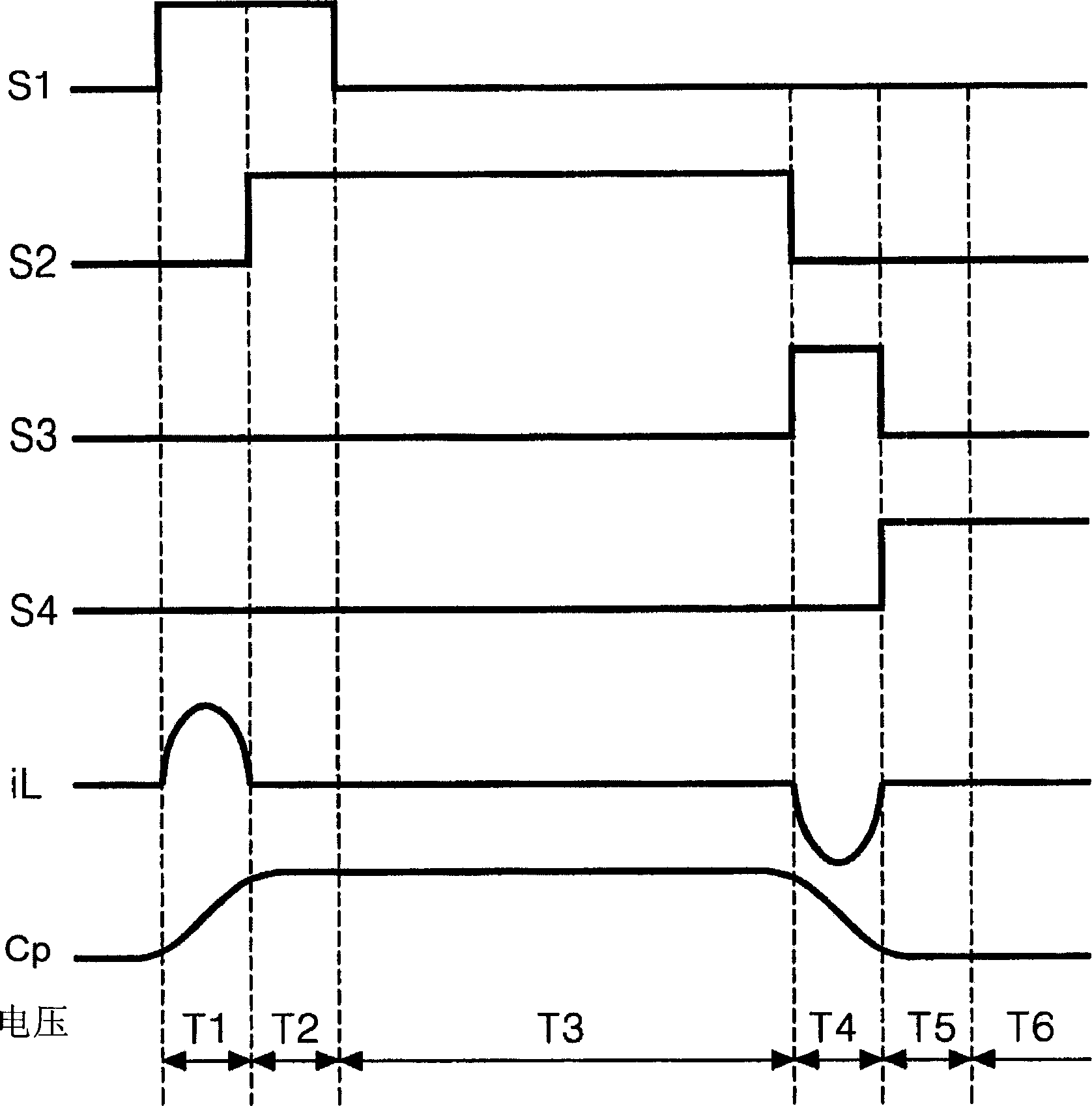
[0034]In order to achieve the above object, according to one aspect of the present invention, the provided energy recovery device includes a capacitive load equivalently formed between the scan electrode and the sustain electrode, which is used to recover the energy charged into the capacitive load and restore the recovered energy An energy recovery unit provided again to the capacitive load, an energy supply unit disposed between the energy recovery unit and the capacitive load, wherein the energy supply unit relays energy between the energy recovery unit and the capacitive load, and supplies the capacitive load a reference voltage to generate a stable discharge in a capacitive load, and an energy relay unit disposed between the energy recovery unit and the energy supply unit for connecting the energy recovery unit and the energy supp...


PUM


Abstract

The invention relates to a energy recovery device for plasma display board, which comprises capacitor load equivalent formed between scanning and maintain electrodes, a energy recovery unit to recovery and provide energy charged in capacitor to capacitor again, a energy supply unit between recovery unit and capacitor to relay energy from capacitor and energy recovery unit, provide reference voltage to capacitor load and generate stable discharge in capacitor, and an energy relay unit arranged between energy recovery and supply units to relay energy between said units. This invention needs no diode to decrease cost.

Description

technical field [0001] The present invention relates to a plasma display panel, and more particularly to an energy recovery device and method for a plasma display panel. Background technique [0002] The plasma display panel (hereinafter referred to as "PDP") is suitable for displaying symbols or graphics by emitting ultraviolet light with a wavelength of 147nm generated during the discharge of an inert gas mixture such as He+Xe, Ne+Xe or He+Ne+Xe. Image. Such a PDP is easy to be made large and thin, and can provide significantly improved image quality with the recent development of related technologies. Specifically, the three-electrode AC surface discharge type PDP has the advantages of low driving voltage and long product life since wall charges accumulate on the surface during discharge and electrodes are prevented from being sputtered by discharge. [0003] figure 1 A perspective view showing the structure of a discharge cell of a conventional plasma display panel. ...

Claims


Application Information

Patent Timeline
Patent Type & Authority Applications(China)
IPC IPC(8): G09G3/28G09F9/313H01J17/49G09G3/288
Inventor 刘知昇
Owner LG ELECTRONICS INC
Why Eureka
Try Eureka